Contents
- 1Introducing the Enermax MaxPro 600 W (EMP600AGT)
- 1.1Packaging and accessories
- 2Connectors & cabling
- 2.1Casing & cooling
- 3Input filtering
- 4Primary side
- 4.1+5 V stand-by rail
- 5Secondary side
- 5.1Build quality
- 6Load testing
- 6.1Loading +5 V SB
- 6.2Hold-up time
- 6.3Combined loading
- 6.4Combined loading ripple
- 6.5Crossloading, overloading
- 6.6Crossloading, overloading ripple
- 6.7Fan speed, temperatures and noise
- 7Conclusion and evaluation
- 7.1Thanks
- 7.2Discussion
Secondary side
On the secondary side of the EMP600AGT sit the schottky diode rectifiers. There are three PFC Device Corporation PFR30L60CT (30/250 A at 60 V, drop of 0.6 V at 15 A and 25 °C) in a TO-220 package, plus a spot for a fourth one for the +12V rail. The +5 V rail uses the Silan Microelectronics SBD30C45T (30/200 A at 45 V, 0.7 V). The +3.3 V has the beefy TO-247 MBR3045PT (30/200 A at 45 V and 125 °C, 0.65 V at 20 A and 25 °C). The +3.3V rail is derived from the +5 V using a magnetic amplifier circuit. As for the common inductors, they seem capable enough. The inductor for both the +5 V/+12 V rails also has a small winding to generate −12 V. Most of the caps on the secondary are more C(r)apXon GF or KF 2200/16 and 3300/10, plus a Su’scon MF 1000/16 for the −12 V rail. That is just garbage if you ask me.
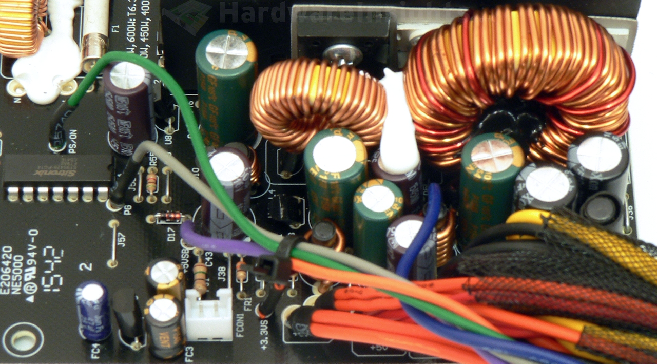
The fan regulator uses a thermistor sensor. As usual for these cheap CWT platforms, it is just placed close to the secondary heatsink without thermal compound or any firm physical contact to it. There’s also a LM393 dual comparator from UTC in the fan driver circuit. The secondary monitor is the Sitronix ST9S429-PG14, and besides providing the ordinary functions (Power Good, monitoring PWR On) it also monitors OCP, OVP, and UVP.
Build quality
As usual, I’ll focus on the overall build quality and other things like electrical safety here, as the quality of the components that were used has already been discussed before. The separation between the primary and secondary side is good. The varistor is sleeved while the thermistor is not. I think thermistors still go bad from time to time, and when they do they usually burst into flames, so it could use some heatshrink. Component insulation is mostly good. CWT used slightly more glue to hold components in place than they usually do. Paths meant for conducting most of the current are reinforced both by wire jumpers as well as solder, which is the usual for CWT.

The design is clean but as it is a cheaper one, the soldering is not the best. Many joints could use a greater amount of solder or even a supplementary resoldering after the wave soldering. Channel Well most likely think that their wave soldering is fine for the most part as I only found a single manual repair. I found a single stray solder ball this time which is good. But due to the lackluster soldering which did not impress me, I’ll be deducting 3 points. By the way, note the bare piece of PCB on the left side. I think it was supposed to be broken off (as it is in fact partially cut from both sides) but they somehow missed it…

