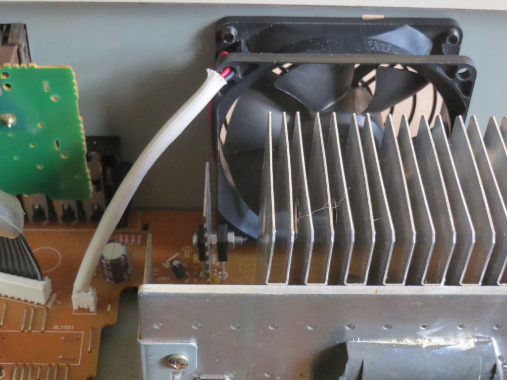
- New fan and modified controller.JPG (273.63 KiB) Viewed 75105 times
As I mentioned in
the micro-review, I indeed went with the salvaged Nidec D08K‑24PH fan. However, I tried a different approach to regulating the supply voltage: Instead of dropping the input to a 7824 with a Zener diode, I decided to rebuild the original control circuit with some modifications.
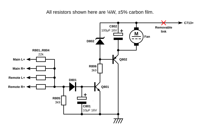
- SU-Z780 fan controller.png (30.01 KiB) Viewed 75105 times
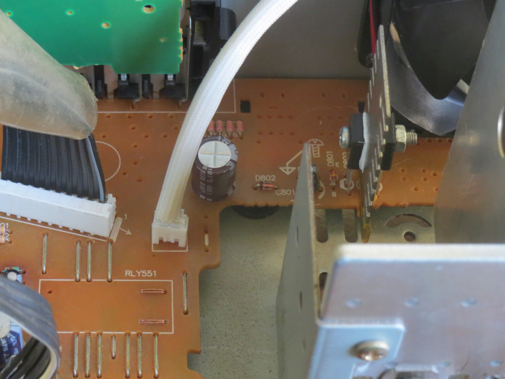
- Controller.JPG (247.07 KiB) Viewed 75105 times
Originally this circuit was powered from a lower voltage, but there's a link that can be removed to disconnect it from there (even though it doesn't cross over any other tracks); I then patched it onto the main +42V (using a solid Cat5e core on the underside). I replaced Q802 with a BD140 on a small heatsink (originally for the 7805 in an early ATX PSU, though unfortunately only made of steel), and Q801 with a BD139 (overkill power-wise, but it's what I have with the correct pinout and doubles as additional anchorage for the heatsink). Preliminary testing with a 12V fan (Power Logic PL80S12M from a Macron PSU) and two 4.7V 1W Zeners (what I had) in series worked OK, although Q802 got quite hot (given the rated 140mA draw of the PL80S12M, it would have been dissipating about 4.2W); I then got some 24V 0.5W Zeners (along with 22V, 20V and 18V versions in case I want to slow the fan down) in my last Mouser order, and replaced C802 (originally 100μF 16V Panasonic SU) with a 220μF 35V Nichicon PW. I also found the
matching header as used in the Kyocera laser printer I salvaged the fan from, and installed one in place of the original header. With calculated dissipation down to 1.26W, Q802 stays much cooler now.
(In doing this fan mod, R806 should be upgraded to at least ¼W. If you have a higher original supply voltage, it may even have to be ½W; or you could up its resistance as long as it still provides enough base current for the Q802 replacement of your choice.)

- D08K open.JPG (257.95 KiB) Viewed 75105 times
These Nidec D08K fans are also unusually easy to oil the sleeve bearing in; simply twist-unlock the impeller by turning it in reverse while gently pulling it.
After oiling, just insert the impeller and rotate forward to lock back in.
- (scratches were from my rotary tool kicking itself out of the hole while extending it; don't use a handheld drill for the holes if you have a drill press)
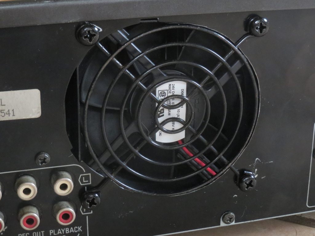
- Back.JPG (247.71 KiB) Viewed 75105 times
I found that FSP use M5 screws to mount the fans in their PSUs, and if anything they actually give a stronger grip than the usual self-tappers; I bought some other M5 screws (10mm long) and nuts at Bunnings, and since these (made by Pinnacle Hardware) have better threads (without noticeable triangular distortion), they hold stronger still. (Initially I got zinc-plated as normal, but later saw some black versions and got them to match.) In theory M5 screws might be too tight with the stated 4.3±0.3mm mounting hole tolerance (I believe 4.8mm self-tappers are recommended), but I got away with it here (despite the high torque).
In the worst case, you could use a reamer. It seems to me that speed of installation is the only
real advantage of self-tapping screws.
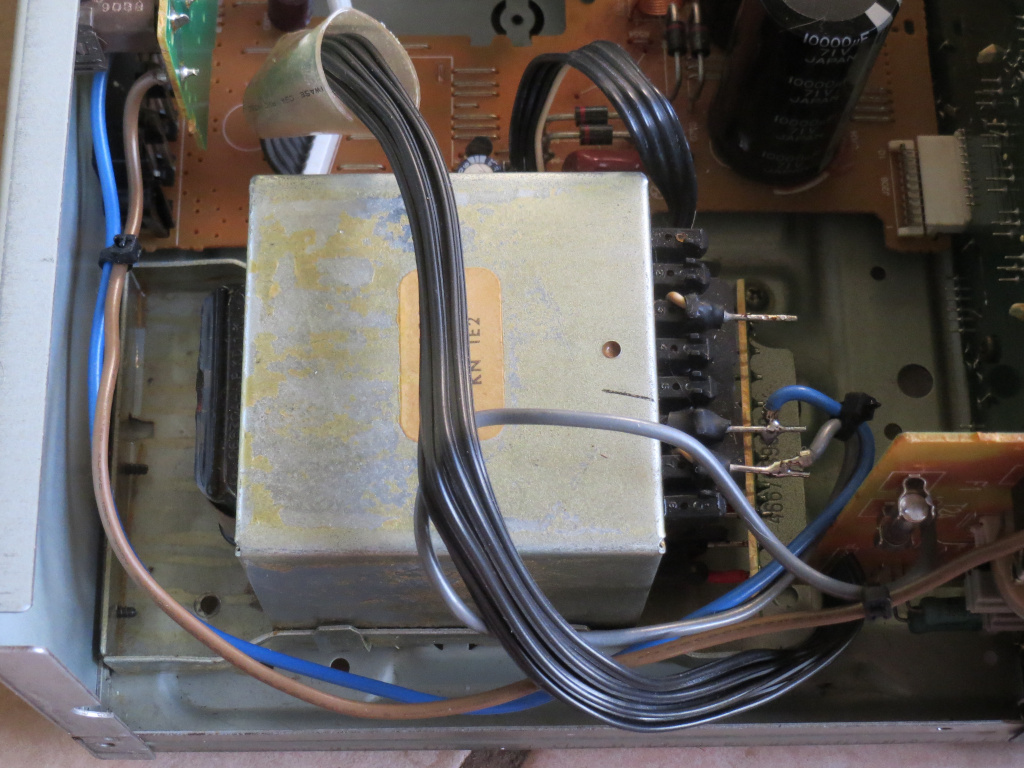
- Transformer.JPG (316.62 KiB) Viewed 75105 times
The transformer was evidently also replaced observing the bodged mounting, previous screw marks in the bracket, and that the mains wires are soldered straight to the pins (quite ugly, and even with the AMP-In type end reinforcements, I doubt that's up to standard in a metal-cased device which is supposed to be Class II

) instead of into a PCB. Also, there are remnants of solder even on the “unused” pin (connection between the primary winding and thermal fuse).
I added a few cable ties to the mains wires for at least a little more peace of mind. A further travail awaited as I noticed the output level bar-graphs dimmed as more segments turned on; however, they're driven by the
BA6144 which has constant‑current LED outputs (nominally 15mA each), so what gives?
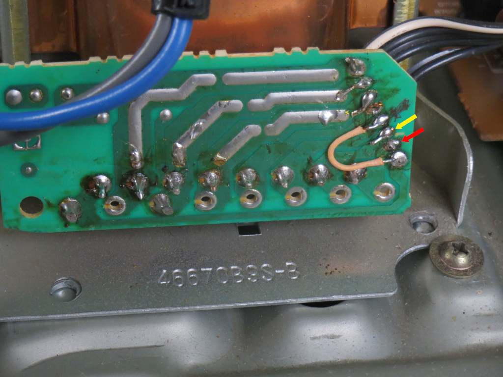
- Wire 4 was put where the red arrow points in the previous "repair", I moved it to where the yellow arrow points.
- Transformer connections.JPG (303.25 KiB) Viewed 75105 times
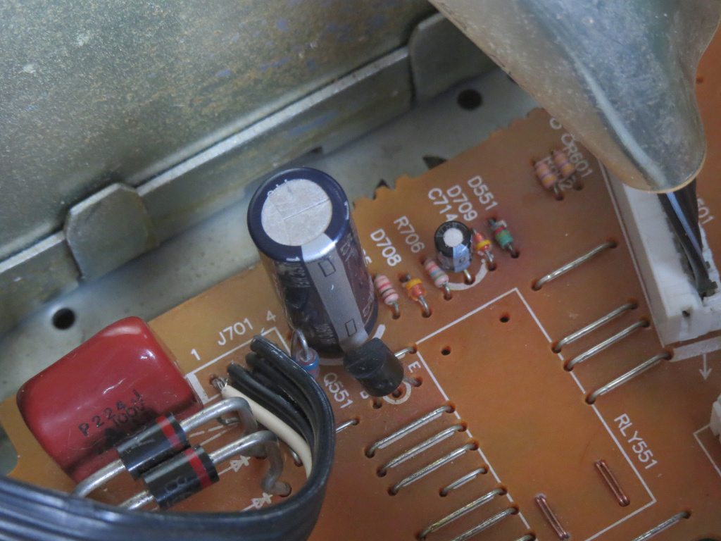
- HFA1000-25.JPG (289.14 KiB) Viewed 75105 times
It turns out that the supply rail to the meters, which should be around +9V to +13V (comparing the installed 2×33Ω anode resistors with the suggested values), was down around +4.7V; I managed to find a winding giving 2×11.4VAC or thereabouts (was probably an auxiliary supply in the original application) and rewired to one half of that, changing C713 (470μF 16V Panasonic SU) to a 1000μF 25V Panasonic HFA (salvaged from a Compaq-proprietary Hipro PSU years ago) to be on the safe side. I also upped the anode resistors from 2×33Ω ⅛W to 47Ω + 68Ω ¼W (per side) to better-fit the datasheet recommendation.
(I actually found out the hard way that the auxiliary winding's center tap has to be grounded separately, and in hindsight, it would have been possible to put it on the ≈3.8VAC winding to get ≈7.6VAC from the anti-phased half of the auxiliary winding. But I'm not putting the PCBs through
another round of desoldering just to change the components back…)
Now the level graphs maintain a nice steady brightness, and also the Super Bass LED (very dim before) lights properly (it has its own current source using discrete components, which was also in drop-out under insufficient voltage).
Observing that the bulk capacitors (C703 and C704) are rated for 71V, the original supply (and hence main secondary) voltage would also have been somewhat higher; output is suggested as 110W peak into 8Ω, but ±42V supplies could only manage that with a perfectly rail-to-rail output stage

.
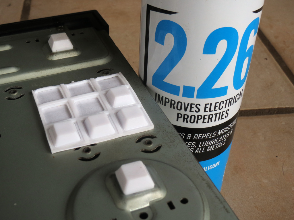
- Feet, CRC.JPG (241.08 KiB) Viewed 75105 times
Potentiometers were cleaned by squirting CRC 2.26 (probably too much of it

) into them and turning end-to-end several times. One of the 4 felt feet (rear-left corner nearest the transformer, possibly due to the heat) was missing, so I replaced them all with some 13×13mm EHI Surface Gard white bumpers (SKU 17582 which doesn't seem to be listed on their site; only larger sizes were available in black, at Bunnings). Based on the feel I guessed they're thermoplastic elastomer (TPE), and later confirmed by sacrificing part of the webbing (it melts on a soldering iron, and unlike PVC would continue burning once ignited).
One of the replacements came off shortly due to inadequate cleaning of the old adhesive (it was hard to remove), so I went at the area with a wire brush (by this point I'm not too fussed about wearing off the zinc).
To get the headphone output down to a safer level for modern headphones (and also lower the output impedance to something reasonable), I added 4.7Ω resistors across each channel out (forming a voltage divider with the original 330Ω 2W series resistors).
In a newly-designed product (if it didn't have the budget for a separate headphone output stage) I would actually use parallel pairs of shunt resistors so that a broken connection there wouldn't cause a
totally deafening output volume, but that'd be a bit cumbersome to add as a modification.
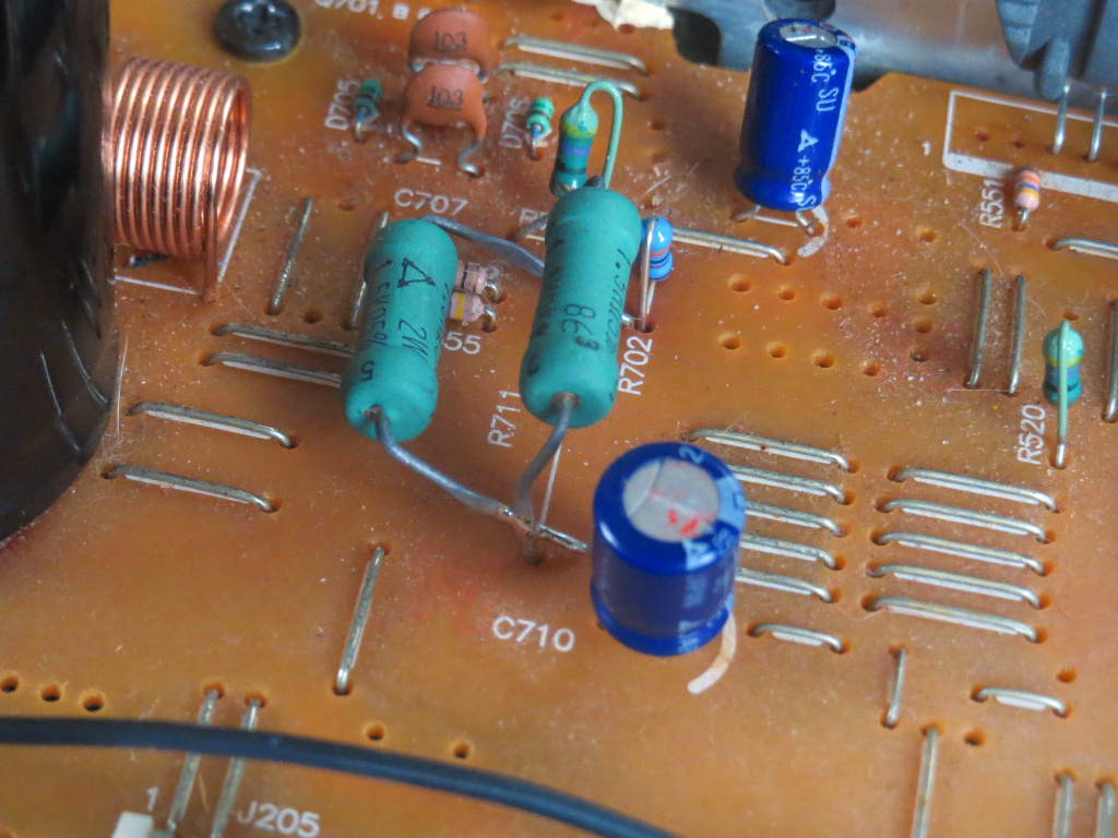
- Resistor change.JPG (335.31 KiB) Viewed 75105 times
However, that still wasn't enough; when testing with a sinewave into load resistors, I only got around 10V RMS (12.5W/channel into 8Ω) before clipping (and even instability), and even at that level surprisingly severe crossover distortion appeared on the oscilloscope

. It turns out that one or both of the power module and transformer replacement (they were probably replaced together given that the original power module was a different type) had messed up the bias network, so it couldn't uphold the required −15V; it uses a Zener diode (D706) fed by a 1.5kΩ 2W (R711) in series with 270Ω ¼W (R702). Observing an example circuit for the
SVI3102 (that's about all I can find on it

), the recommendation is 780Ω (two 390Ω 2W in series). But I was able to remove an identical 1.5kΩ 2W (R553) from the now-unused relay circuit, and tacked their leads together in parallel, also changing R702 to a 33Ω ¼W (although calculating it now, I could have reused one of the original 33Ω ⅛W resistors). If your unit has been altered in the same way, then the neatest resistor change would be to a 680Ω 2W + 100Ω ¼W (or 750Ω 2W + 30Ω or 33Ω ⅛W if you stock E24 values). I also swapped the two AC sense resistors (R555 and R556), which were located backwards compared to the example circuit; but I don't know if that's had any functional change. After that, it manages about 35W/channel into 8Ω (or 45W one at a time) clean, which is as good as it will get with the wimpier replacement transformer (supply rails drop to around ±28V).
Only my load resistors get dangerously hot

, temperatures of everything else seem under control. In theory D706 now has a marginal power rating, but it isn't getting too hot to touch so it might be OK; still, I've included a 1W replacement in my next order to be safe.
One final malfunction showed up after moving house: The input selector changed spuriously, most often returning to the Tape input. I first thought it was from interference in the new location and added 220pF capacitors from the control pins (11..15 and 17 on the LC7818) to ground (pin 16), but that had no effect; I tried bridging out the transformer ground wire (which I thought might have broken, as the ribbon cable suffered a lot of stress during prior repair work) with an offcut of 1mm² flexible earth core (with ferrules crimped on the ends, just for quicker soldering really) from the transformer PCB to the nearest ground link (after grinding off the oxidized tin), but that didn't completely solve matters; I then replaced the entire ribbon cable with an off-cut FDD power lead (shuffled so that its black wires became the two interchangeable 30Vac taps, with yellow ground and red for the preamp winding) and pin header on the board (if I had to
buy it I'd have obtained the proper keyed header, but here I used a leftover pin strip from a cheapo Freetronics Arduino kit), after which I found during testing (with the load resistors) that a strange buzzing occured with the main speaker switch off (remote switch on, load resistors on remote speaker terminals), but not with it on.
It
shouldn't have done that, since the remote speaker switch takes priority

anyway I squirted yet more CRC 2.26 into it (and the speaker ribbon header for good measure), and so far so good.
Finally I replaced the feet again with some 3M felt pads (circular ¾″/19.05mm, but they do the job anyway), since those elastomer bumpers were gripping my desktop
too well and kept tearing the adhesive off

.
It now resides beneath Mum's HDD recorder (and second-hand Blu-ray player), so I can actually
listen to what little is worth watching on the (“smart”) TV…
In case you're wondering what an original unit looks like, try
here.