Contents
- 1Introducing the Linkworld LPW1685-70
- 1.1Packaging and accessories
- 2Connectors & cabling
- 2.1Casing & cooling
- 3Input filtering
- 4Primary side
- 4.1+5 V stand-by rail
- 5Secondary side
- 5.1Build quality
- 6Load testing
- 6.1Loading +5 V SB
- 6.2Hold-up time
- 6.3Combined loading
- 6.4Combined loading ripple
- 6.5Crossloading, overloading
- 6.6Crossloading, overloading ripple
- 6.7Fan speed, temperatures and noise
- 7Conclusion and evaluation
- 7.1Thanks
- 7.2Discussion
Primary side
The primary side of the LPW1685-70 starts with an input bridge rectifier, the GBU806. This one handles a current of 8 A continuous at 100 °C or 200 A peak surge (for 8.3 ms) at 600 V. It has its own aluminium heatsink mounted to it. The voltage drop is 1.0 V per diode at 4 A. The PFC consists of a medium sized PFC choke with rather thin wire for the winding. There will be some losses in the choke so it may run somewhat warm. There are two transistors used for the boost stage, the Magnachip MDF13N50 (13/52 A at 500 V and 25 °C, RDS(On) 0.5 Ω at 6.5 A) in a TO-220F package. The diode in the circuit is the NXP BYC10-600 (10/71 A at 600 V and 78/25 °C, drop of 1.8 V at 10 A and 150 °C, 2.9 V at 25 °C) in a TO-220AC package. These three devices share their own aluminium heatsink.
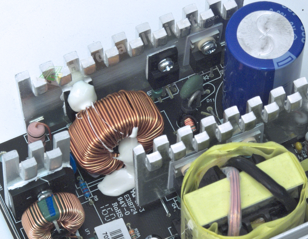
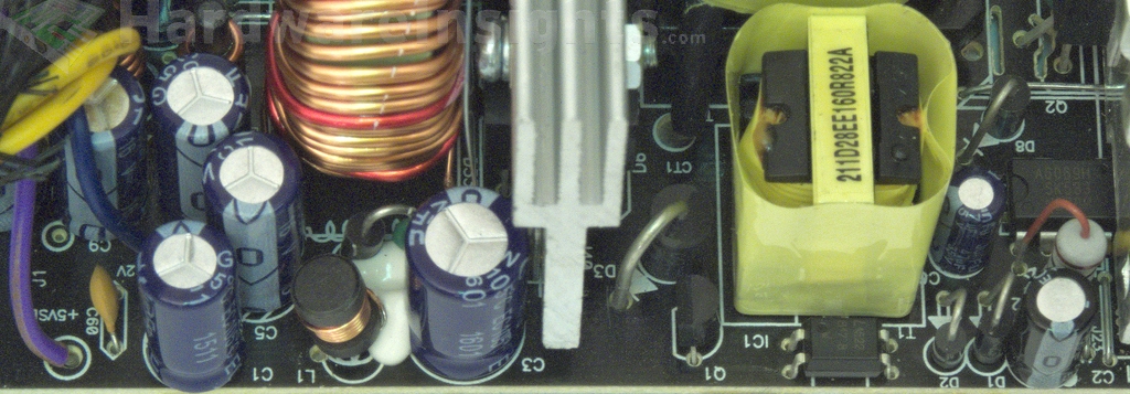
The capacitor charged by the PFC circuit is the Hitachi HU 330 μF/420 V, which measures at 297 μF. This series is rated for 2000 hours at 105 °C at its maximum rated ripple current. It is quite a nice surprise to find a quality capacitor in such unit. The main switchers are also from Magnachip, but higher-performance, MDP18N50 (18/72 A at 500 V and 25 °C, RDS(On) 0.27 Ω at 9 A) in a TO-220 package and the usual two-transistor forward configuration. They have their own dedicated aluminium heatsink.
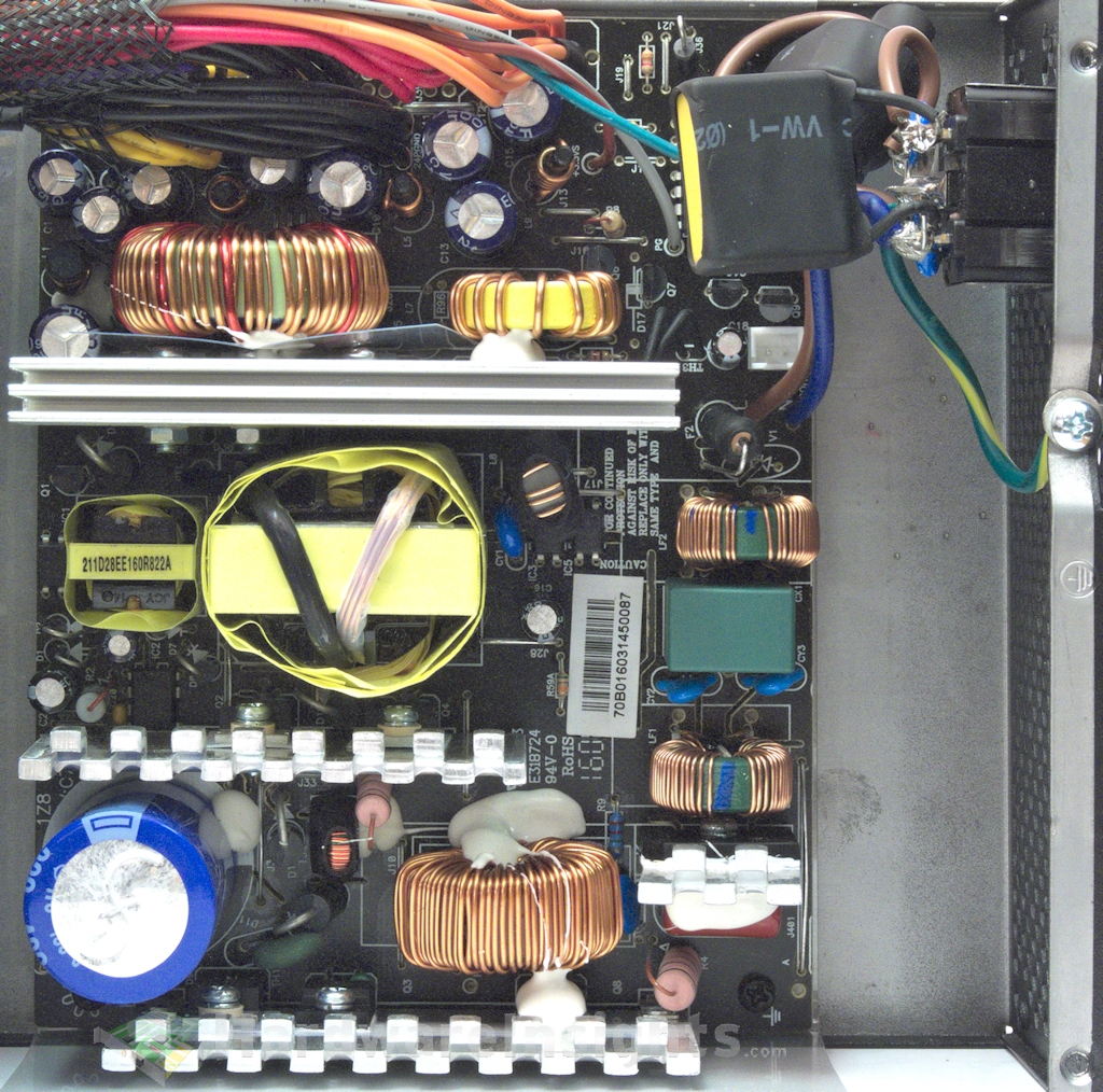
As could be expected, a Champion Micro controller has been chosen to drive the unit. But it is not the usual CM6800, rather the CM6805BG. This is a cheaper controller but CM claims it can reach similar results. Linkworld (or more likely Andyson) used the funds to buy second CM chip, the CM03X, to save power by reducing the no-load consumption. A JunFu HX 47/50 capacitor is used for filtering the power supply for the CM6805BG. The main transformer is an ERL-35 type which should be enough for 700 W at this efficiency.
+5 V stand-by rail
The stand-by power supply uses PWM driver with an integrated MOSFET from SanKen, the STR-A6069H. This driver can supply up to 10 W continuously with 20-40 % more depending on the design. The oscillator frequency is fixed at 100 kHz and the integrated FET has RDS(On) rated at 6 Ω. Another JunFu capacitor is used to filter its own power supply, WG 47/35. The transformer is ‘EE-16’.
A schottky diode in a DO package rectifies the transformer output. There are more garbage capacitors to filter the output, namely WG 1000/16 and 1000/10. Let’s move on…

