Contents
The repair
First you will see insulation foil over the power board, remove it but don’t lose it (and don’t forget to place it back after the work is done!). Remove all screws from both boards, do not forget the hexagonal screws by the D-Sub and DVI connectors. It is better to remove both the boards at once since they are connected with 8pin connector directly one into the other.
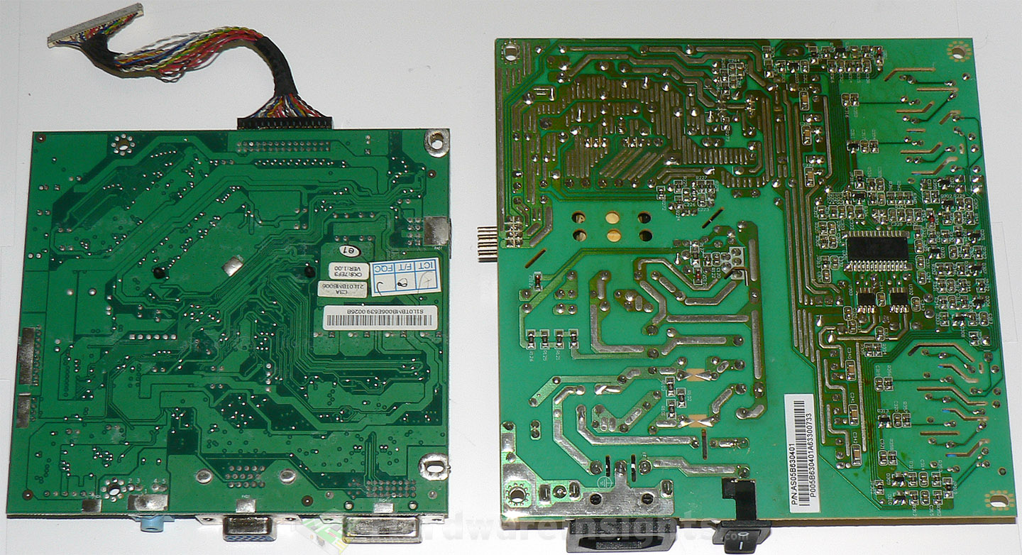
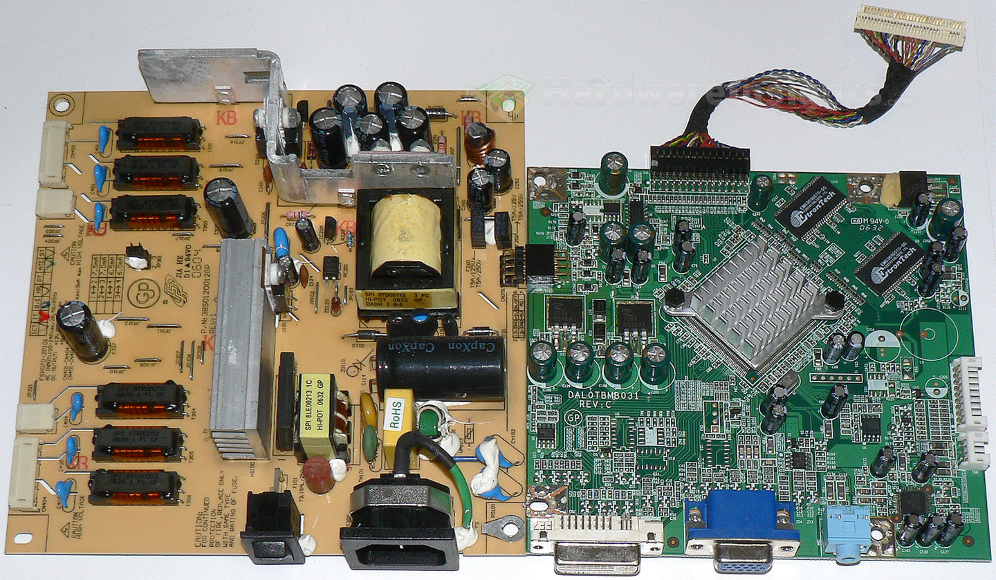
The power board, made by FSP Group (Sparkle) has usual topology with PWM regulator carying integrated transistor in a single TO-220 derived casing. That is why it has five legs. On the output, there are three rails: +5 V and +12 V for powering the signal board and the panel, and a third rail for inverter. Unfortunately, I do not remember the voltage for inverter.
(But you can easily measure that. Place the power board onto something non-conductive, components down. Connect a power cord to the board and then very carefully to electricity. Then, with extreme caution, you can measure voltage over the capacitor in the inverter section. If you are not up to it, let somebody with more skill do it for you. You need to discharge the main capacitor after unplugging the board from electricity, you can do that with your multimeter while observing the voltage on it, which is up to 325 V peak on 230V AC.) The reason to measure the unknown voltage is to discover what are the right capacitors for you. You can of course just use the original voltage rating, but often you can lower the voltage and increase capacitance because the real voltage in there is much lower than the rating of the original capacitors.
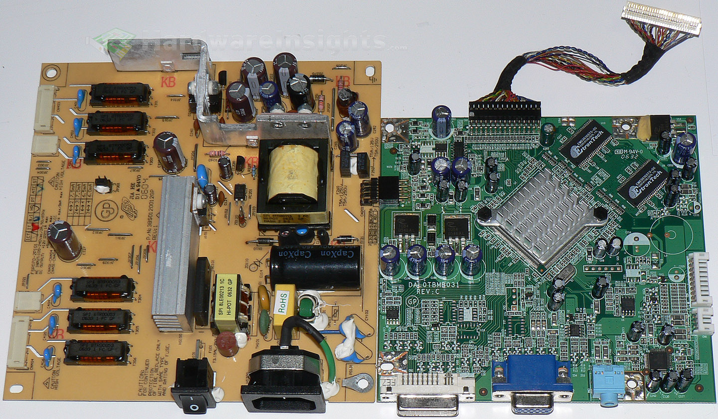
In this case, almost all c(r)apacitors were blown visibly, that is terrible. Even if they are not yet bad on your logic board, I strongly recommend replacing them anyway, it is only a matter of time. Including the small ones; I have also seen several of them gone bad. So basically full recap (though the input capacitor is usually OK, but you should at least measure it). For the power board, from my offerings, you can use Chemi-Con KZN 1500/6.3 for +5 V rail, KYA 1500/16 for +12 V rail and 1000/25 or 680/35 for the inverter rail, depending on its voltage. For the signal board, KZM 470/16 (or later 680/16), the small ones are mostly 100/16, 22/50 and 10/50 if I recall it correctly.

After the recap and re-assembly, the display should now turn on OK. However, I have seen another problem with this display even after full recap, which often also happen to AL2023W and sometimes even AL2423W as they all use the same logic board. Often the display starts blinking during start-up and than later, it starts ghosting NO SIGNAL message over the picture. I have no idea what the problem is, there does not seem to be any certain cure, but unplugging the monitor from electricity for some time for each night helped for me. I suggest turning the AC switch off for the night for some time, a week or two. Than you may try to keep the AC on. But I still strongly suggest to power the display off using its on/off switch, not leaving it in stand-by (the orange backlight of the button must turn off).
I suggest this for ALL displays, it puts slightly less stress on them. If the problem returns, you may always keep it turning off for some time. Worst case scenario is to turn the wall power off each day, than it should never happen again in the morning. After the customer returned this unit to me, I kept it and I have not seen this problem since. It sometimes loses the power when an UPS beneath it I am testing with ditched batteries dies (because the already quite bad batteries drain completely very quickly and the UPS cannot hold the power) so it basically gets the AC power cycle, but I think it may actually be good even without that. I forgot turning it off over night after maybe two months. Including the UPS time, it is now 8 months and still no strange behaviour.
Pages: 1 2

