Contents
- 1Introducing the Cooler Master V650
- 1.1Packaging and accessories
- 2Connectors & cabling
- 2.1Casing & cooling
- 3Input filtering
- 4Primary side
- 4.1+5 V stand-by rail
- 5Secondary side
- 5.1Build quality
- 6Load testing
- 6.1Loading +5 V SB
- 6.2Hold-up time
- 6.3Combined loading
- 6.4Combined loading ripple
- 6.5Crossloading, overloading
- 6.6Crossloading, overloading ripple
- 6.7Fan speed, temperatures and noise
- 7Conclusion and evaluation
- 7.1Thanks
- 7.2Discussion
Secondary side
As we have already established, the V650 synchronous rectification is driven by the CM6901TX. It is connected to the primary side using dual-driving Silicon Labs Si8230BD isodrivers (two for each pair of transistors). The rectification itself uses two pairs of Infineon IPP041N04N G (90/400 A at 25 °C and 40 V, RDS(On) 2.3 mΩ at 90 A) transistors in a TO-220 package. If they had a slightly bigger heatsink (or transferred their heat to the chassis through better thermal coupling) I think the unit could very well have been semi-fanless. Notice the two thermistor probes mounted to it: the right one provides feedback for the fan controller, the left one is for OTP. The Unisonic Technologies 2SB772L (-3/-7 A at -30 V) PNP transistor acts as the linear regulator for the fan. The filtering capacitors for the +12V output are two Unicon UPT 820/16 polymers and three NCC KZE 2200/16 wet electrolytics. Two more 330/16 polymers are on the input side of the two DC-DC modules (so there are four of them altogether).
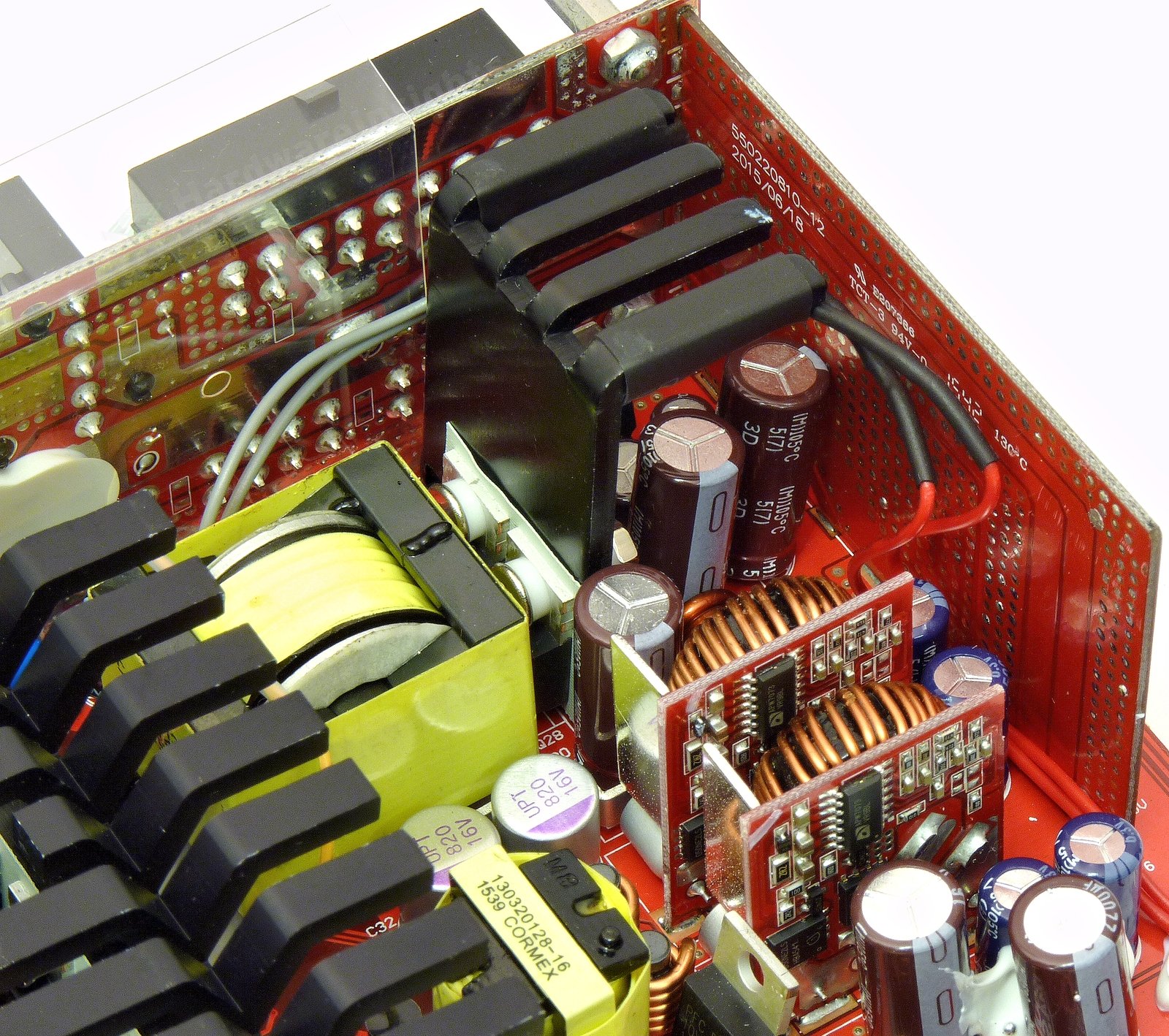
The DC-DC modules are still relatively small, each on a separate board, but this time they used ordinary transistors and not the Texas Instruments power block. The FETs are one Infineon BSC018NE2LS (100/400 A at 25 °C and 25 V, RDS(On) 1.8 mΩ at 30 A and VGS of 10 V, 2.3 mΩ at 4.5 V) and one BSC050NE2LS (58/232 A at 25 °C and 25 V, RDS(On) 5 mΩ at 30 A and VGS of 10 V, 7.1 mΩ at 4.5 V) on each board. They both come in the PG-TDSON-8 package and an Anpec APW7073 drives them on each module. Notice the copper plates around the coils on the boards for cooling and EMI shielding. Output is filtered by another 330/16 polymer and two pairs of custom Chemi-Con LXZ 1500/6.3 capacitors. The −12 V rail has an ST Micro L7912CV3 voltage regulator to raise the low negative voltage to a stable −12 V output, and it uses an NCC KY 220/25 on the input and a 100/25 on the output. There is one more UPT 330/6.3 for both the +3.3 and +5 V rails on the modular board plus one Suncon Sunelec WX 220/16 for the stand-by rail. Three more WX filter the +12 V.
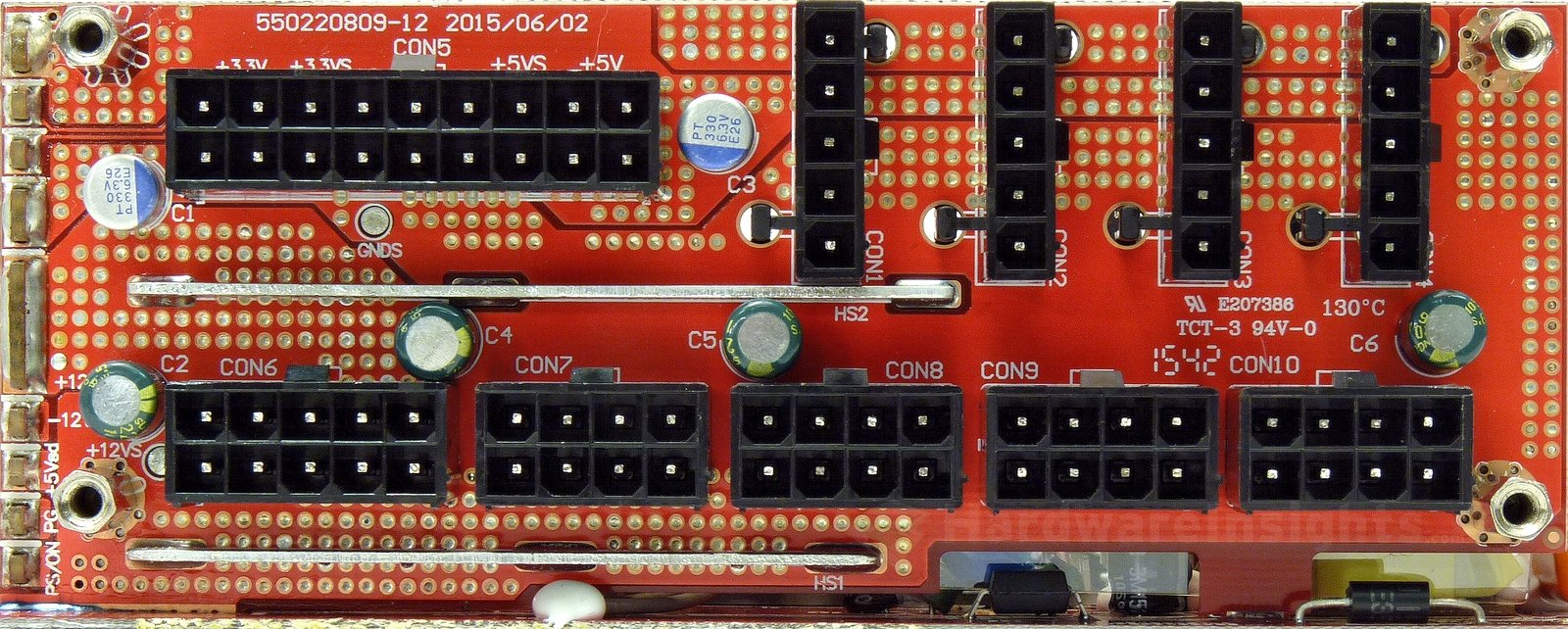
The modular board itself is soldered directly to the main board where it sources return ground from. Another PCB conducts the remaining voltages including feedback sense, PWR Good and PWR On. It is actually a nice idea as it also serves to channel the airflow unlike thick cables which would interfere with it. The secondary supervisor is the Silicon Touch Technology PS223. Besides the ordinary functions, this one also monitors OCP on both 12V rails and also the +3.3/+5 V rails. It also has an input for OTP. I think I’ll throw a point in for the overspec’d silicon the V650 uses on its secondary side.
Build quality
As usual, I’ll focus on the overall build quality and other things like electrical safety here, as the quality of the components that were used has already been discussed before. The separation between the primary and secondary sides is good. As the modular board sits very close to the primary side, there is a protective insulating sheet placed between them. Both the varistor and the thermistor are not sleeved with heatshrink (though the latter will see much less stress because of its bypass relay). The amount of silicone used which serves to secure components in place is adequate. It is also of decent quality, unlike the cellulose type which might degrade over time and become electrically conductive.
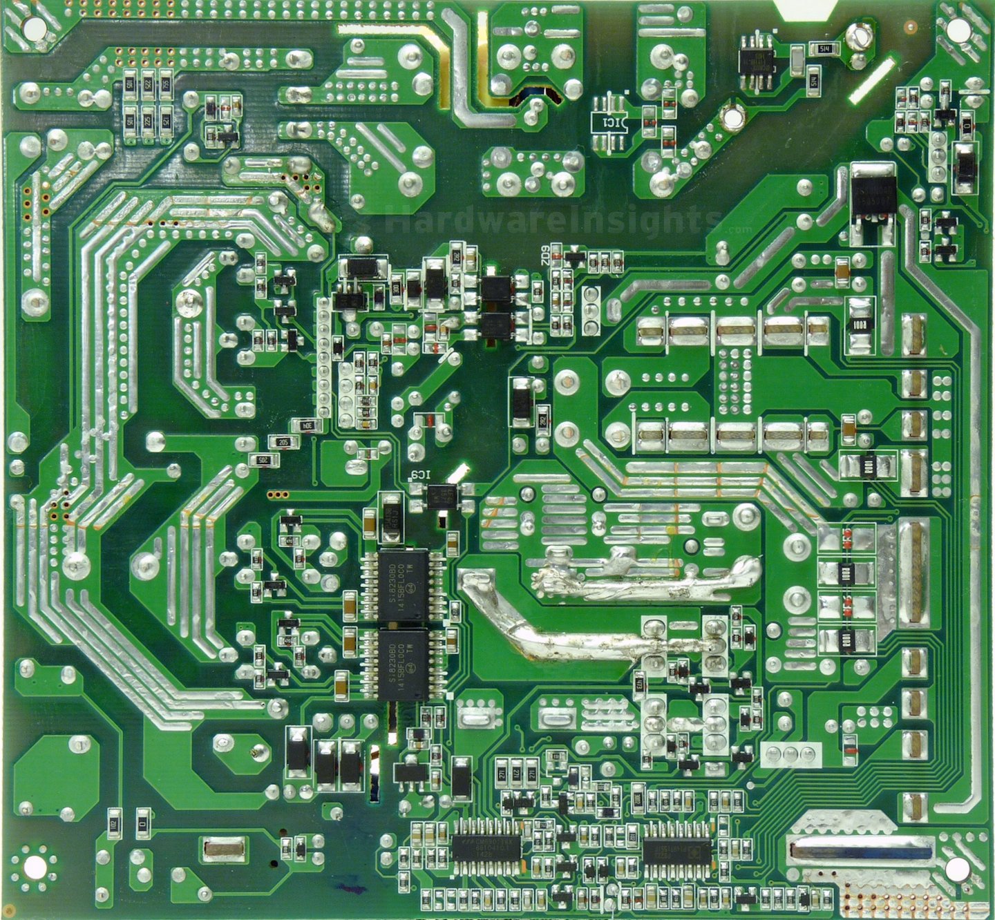
Many of the tracks are reinforced with layers of solder, and the 12V and return paths are also reinforced with some bare wires with large amounts of solder applied around them. There are also copper plates here and there which serve to conduct large amounts of current as well as to help cool the unit. A quality double-sided glass epoxy PCB (or something similar) is used. A few of the component leads could have been trimmed shorter. The soldering quality, however, is still the weak link in Enhance’s manufacturing process. While the solder side does indeed look rather clean, and there isn’t even as so much as a hint of residual flux, (well, except for where they applied liberal amounts around the bare wire used to reinforce the current capacity), and while I did only find three solder balls, it must be said that the wave soldering process they use is quite poor with regard to the quality in which it covers the bare copper. As you can see, large areas remain only very poorly covered. Also, way too many vias aren’t filled from side to side in their entirety with solder. These through-holes basically consist of small holes through the PCB which are coated throughout with copper by copper. In a proper re-flow environment, the solder should wick all the way up the hole. Here, it did not.
The component side is even worse, where most of the naked copper tracks and pads are not completely covered with solder. This is a problem as the copper will oxidize over time without a protective layer of tin (albeit slowly, but it will still definitely oxidize) and the by-products of said oxidation (especially the copper oxide) can act as significant insulators. In fact, some oxidation is even already apparent out of the box. On top of that, the board looks untidy with random patches of residual flux here and there, as well as areas that have been splashed with hot solder during the re-flow process. With this level of soldering quality, one could deduce that what is most likely is that if Enhance did indeed actually attempt to cover everything properly with solder, there would have been too much solder splash as well as too many stray solder balls (and Enhance must have been troubled by this). The previous Enhance units I’ve had on hand always had different problems with regard to soldering, ranging from dozens of solder balls to this. That includes the very expensive Silverstone Strider Titanium 600 W. They really ought to finally address this, as this is the fourth Enhance unit I’ve had, and though most likely the best so far, still hardly good. This time it will result in the deduction of five points.

