Contents
- 1Introducing the Corsair SF600
- 1.1Packaging and accessories
- 2Connectors & cabling
- 2.1Casing & cooling
- 3Input filtering
- 4Primary side
- 4.1+5 V stand-by rail
- 5Secondary side
- 5.1Build quality
- 6Load testing
- 6.1Loading +5 V SB
- 6.2Hold-up time
- 6.3Combined loading
- 6.4Combined loading ripple
- 6.5Crossloading, overloading
- 6.6Crossloading, overloading ripple
- 6.7Fan speed, temperatures and noise
- 7Conclusion and evaluation
- 7.1Thanks
- 7.2Discussion
Input filtering
The input filtering begins with its first stage directly on the input receptacle. There is a piece of PCB soldered to both the receptacle and the single-pole AC switch, and it is then soldered into the main PSU board as a whole. We can see one film X capacitor, two ceramic Y capacitors and also a common-mode choke.
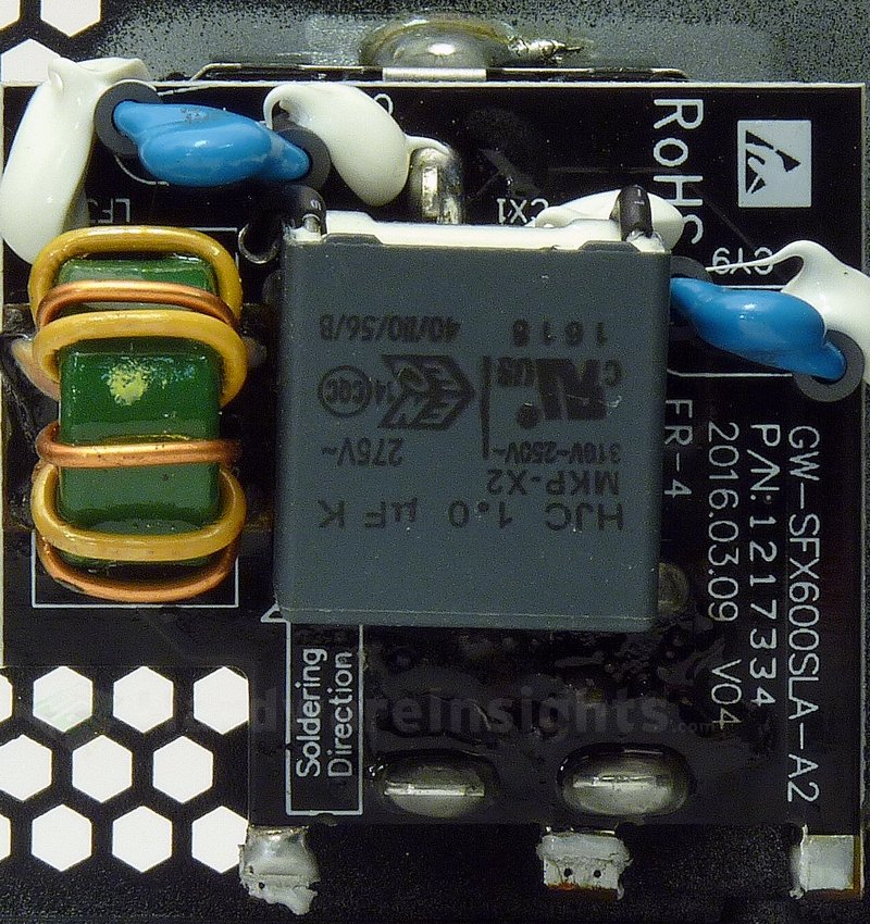
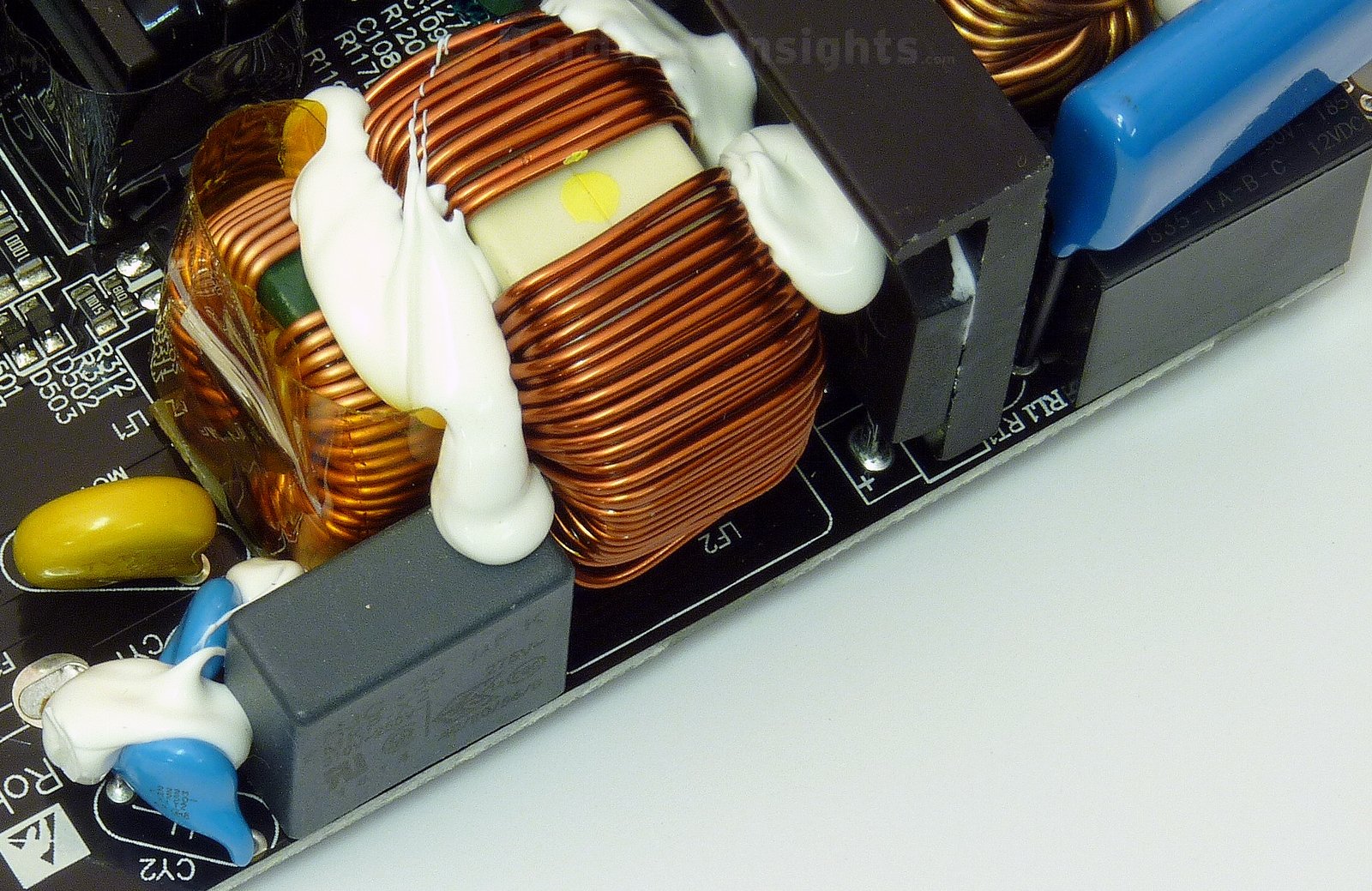
If we move on to the main board, we can see that there are two more Y capacitors (plus a fifth one between the primary common and earth ground, and two SMD ones between the primary and secondary sides). There is also one more X capacitor, two common mode chokes and a varistor (without heatshrink sleeving). On the very right side you can see relay bypass for the heatshrinked thermistor squeezed between the relay and the heatsink.
Corsair has implemented their usual way of discharging the X capacitors through drawing some power from them. In this case it powers two different ICs from them. But that is not all, as this draw is realized behind the input rectifier which is not 100% safe, there actually is X cap discharge microchip. It is some SMD thing in tiny diode-like package which I could not identify even if it was not hiding on the other side of the receptacle PCB.
The X capacitors (between the live and neutral) and Y capacitors (between live and ground/neutral and ground) are used to filter out high-frequency ripple that emanates from the power grid. That is the noise of which manifests in the form of feedback from electronic devices which lack adequate filtering due to cost cutting. But also from devices where filtering was very difficult to implement (powerful devices, e.g. microwave ovens). It also prevents ripple from this unit itself from feeding back into the grid.
Chokes are used for the same reason, and together with the X/Y capacitors they form an input filter. Such filters are often made as one component, they may also be integrated together with AC receptacle. These components may also (partially) help to filter smaller voltage spikes in the power grid. To suppress more serious spikes (for example from distant lightning strikes hitting the power grid), the MOV (metal-oxide varistor) is used. Thermistor is then used to suppress current spikes when first connecting the unit to power (i.e. flipping the power switch).
The Y capacitors are also often situated between the high-voltage primary and the low-voltage secondary sides. These days, more Y capacitors are used even between primary common (ground after an input rectifier) and earth ground to suppress internal interference and keep it from getting to the secondary side. It is because really high-frequency ripple goes everywhere it can to some extent (including coupling through the insulation, metal casing etc…). That is also why the AC wires themselves are often inserted through the ferrite toroid inductor (to suppress such coupling).

