Contents
- 1Introduction
- 1.1Packaging and accessories
- 2Connectors & cabling
- 2.1Case & fan
- 3Input filtering
- 4Primary side
- 4.1+5 V stand-by rail
- 5Secondary side
- 5.1Build quality
- 6Load testing
- 6.1Loading +5 V SB
- 6.2Voltage hold-up time
- 6.3Combined loading
- 6.4Combined loading ripple
- 6.5Crossloading, overloading
- 6.6Crossloading, overloading ripple
- 7Conclusion and evaluation
- 7.1Thanks
- 7.2Discussion
Load testing
Loading +5 V SB
As always, all load testing is done in accordance with our testing methodology. The stand-by supply in the SilentiumPC Supremo M1 550 W had no problem providing both nominal and extra power under a (short) overload scenario. The voltage regulation is somewhat better than in the case of the Silverstone Strider Gold S (based on basically the same platform). With no load it measures 5.17 V and drops only to 5.1 V. So ideally, it should have been set to a default 5.1V and then it would have had much better regulation in relatin to the nominal voltage. The ripple is worse than usual, at over 10 mV. Not out of the ordinary, but we’ve become accustomed to lower numbers.
| Output (W) | Load (A) | Voltage (V)/ ripple (mV) | Input (W) | Efficiency/power factor |
| 0 | 0 | 5.17/12.00 | 0.5 | —/1 |
| 15.09 | 2.95 | 5.11/16.00 | 21.0 | 71.9 %/0.50 |
| 17.48 | 3.43 | 5.10/13.60 | 29.0 | 60.3 %/0.61 |
The efficiency stays above 70 %, but under overload conditions, I started to get some strange measurements at the wall, but I can attribute this to probably being caused by the PFC circuit shutting off and confusing my AC meter. I definitely need to obtain a proper power analyzer for overload conditions.
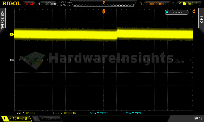
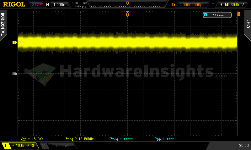
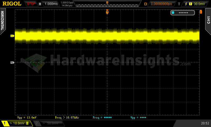
+5 V SB ripple (left to right): 0 A; 2.95 A; 3.43 A
Voltage hold-up time
The hold-up time of the +12 V rail on the scope image is quite good, at 23.3 ms. The voltage steadily decreased to some 10 V because most likely the UVP finally kicked in, but this is already long after I passed the ATX minimum spec (11.6 V). Interestingly, a spike occured when I simulated a long power interruption – the unit later jumped back on but not before immediately turning itself off. This may not be a good sign considering that voltage spiked may occur under normal operation. But it still clearly passes the minimum ATX spec of 16 ms.
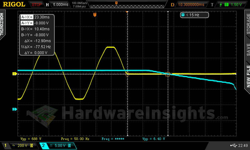
I also simulated a precise 23.3 ms long power interruption (but unfortunately I did not capture the measurement, and I had already reset my oscilloscope for a different measurement). But I did observe an interesting effect, once again there was a spike and the unit once again immediately shut down. So while it meets the ATX spec here, I would still suggest a UPS with this unit if you have an unreliable power grid, as your computer might not like the voltage spikes this unit may produce with very short power interruptions.
Combined loading
Combined loading also went smoothly without major incidents. Once again the −12 V rail seems to lack sufficient turns to produce enough high voltage to feed the regulator with a full −12V load even while the rest of the rails are not even fully loaded. But the stand-by rail still won the race with 5.17 V at no load, that’s 3.4 % over the nominally rated value. Bad Sirtec, bad!
| Output power | Load/ voltage +5 V SB | Load/ voltage +3.3 V | Load/ voltage +5 V | Load/ voltage +12 V | Load/ voltage −12 V | Input power | Efficiency/power factor | Temperature intake/ outtake |
| 5.0 %/ 27.74 W | 0 A/ 5.17 V | 0.040 A/ 3.34 V | 0.267 A/ 5.09 V | 1.876 A/ 12.26 V | 0.291 A/ −11.11 V | 37.5 W | 74.0 %/ 0.71 | 26 °C/ 28 °C |
| 20 %/ 107.12 W | 0.505 A/ 5.15 V | 1.713 A/ 3.33 V | 1.297 A/ 5.09 V | 7.25 A/ 12.26 V | 0.296 A/ −11.26 V | 121.5 W | 88.2 %/ 0.97 | 27 °C/ 30 °C |
| 40 %/ 216.78 W | 0.99 A/ 5.14 V | 3.32 A/ 3.32 V | 2.96 A/ 5.07 V | 14.89 A/ 12.24 V | 0.297 A/ −11.43 V | 237.0 W | 91.5 %/ 0.99 | 28 °C/ 32 °C |
| 60 %/ 324.49 W | 1.95 A/ 5.12 V | 5.14 A/ 3.31 V | 4.24 A/ 5.06 V | 22.3 A/ 12.22 V | 0.304 A/ −11.64 V | 354.0 W | 91.7 %/ 1 | 28 °C/ 32 °C |
|
80 %/ 439.40 W |
2.42 A/ 5.10 V | 6.79 A/ 3.30 V | 6.93 A/ 5.05 V | 30.0 A/ 12.20 V | 0.307 A/ −11.84 V | 481.0 W | 91.4 %/ 1 | 29 °C/ 35 °C |
| 100 %/ 550.13 W | 2.88 A/ 5.09 V | 8.24 A/ 3.29 V | 8.05 A/ 5.04 V | 38.1 A/ 12.18 V | 0.310 A/ −12.01 V | 606.5 W | 90.7 %/ 1 | 30 °C/ 39 °C |
Efficiency was OK with around a 91 % peak, but at low-load tests, efficiency didn’t even reach 80 %. As for the fan, it started off at a very low speed, and increased in speed with the load, yet it never surpassed the noise produced by the fans I use while generating the artifical loads used in my testing. When the load reached very high proportions, the fan started to spin noticeably but was still not audible. The overall unit temperature did also get slightly higher at high loads.
Combined loading ripple
The ripple is on the high side for a high-end unit, but maybe their choice of filtering capacitors played a role here. The worst result was on the stand-by rail with 33.6 mV or 67.2 % of the maximum allowed, alind my standard is up to 40 % for high-end units, so the Supremo M1 is going to lose a few points here.
| Output % | Ripple +5 V SB | Ripple +3.3 V | Ripple +5 V | Ripple +12 V | Ripple −12 V |
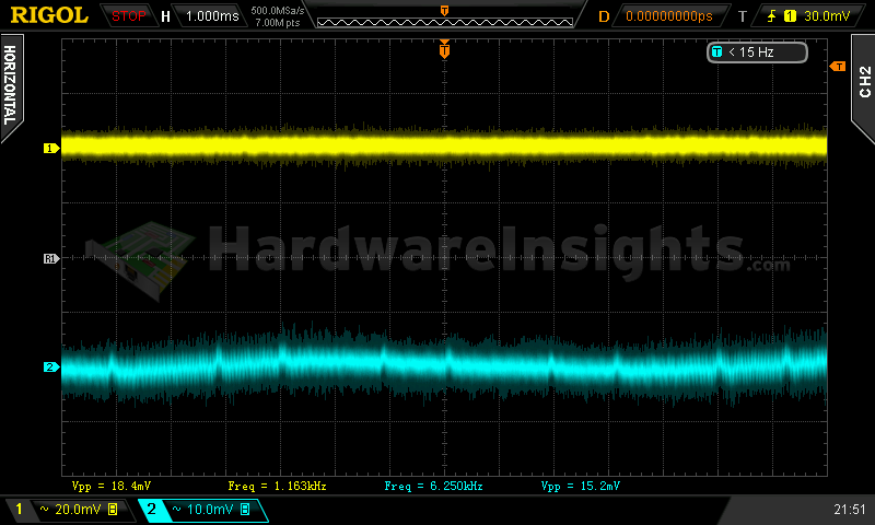
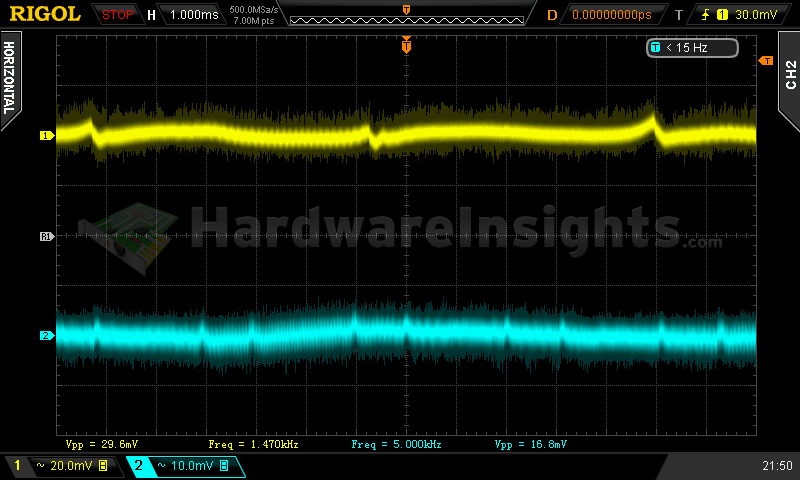
| 5.1 | 20.8 mV | 20.0 mV | 18.4 mV | 17.6 mV | 24.8 mV |
| 20 | 28.0 mV | 21.6 mV | 25.6 mV | 22.4 mV | 29.6 mV |
| 40 | 29.6 mV | 16.8 mV | 26.4 mV | 10.4 mV | 28.0 mV |
| 60 | 29.6 mV | 19.2 mV | 28.8 mV | 8.0 mV | 30.4 mV |
| 80 | 30.4 mV | 24.6 mV | 32.8 mV | 8.8 mV | 33.6 mV |
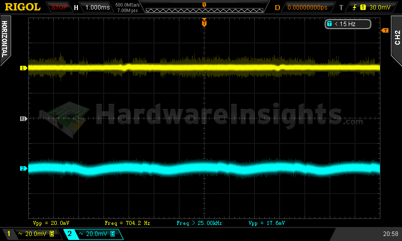
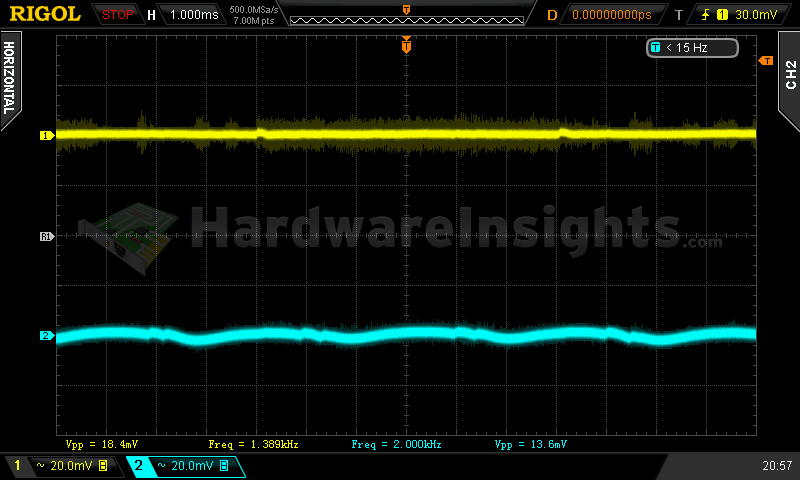
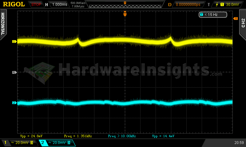
| 100 | 33.6 mV | 18.4 mV | 30.4 mV | 17.2 mV | 29.3 mV |
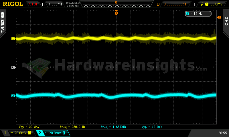
Ripple 5.0% load (left to right): +5 V SB; +3.3 V; +5 V; −12 V. The second channel is connected to +12 V.
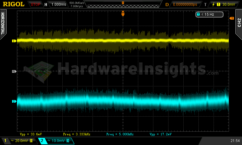
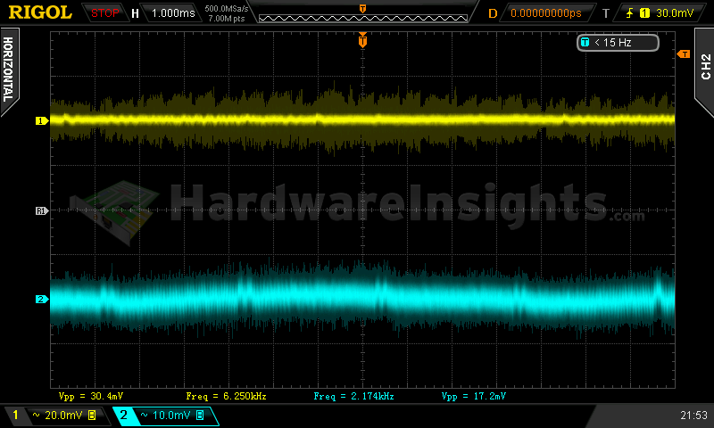
Ripple 100% load (left to right): +5 V SB; +3.3 V; +5 V; −12 V. The second channel is connected to +12 V.
Crossloading, overloading
Crossloading went quite well, but considering this unit’s +12V rail uses DC-DC modules, I didn’t expect anything less. Voltage regulation was somewhat tighter however, and the stand-by supply stayed quite high, at within 3%. The OCP limit was not reached on any rail, and all of them handled the applied overloading without any problems. My attempts to overheat the unit with a sweater were futile, because OTP was activated at not sooner than exactly 5 minutes 19 seconds after the unit was turned on and full load was applied while the fan was inactive.
| Output power | Load/ voltage +5 V SB | Load/ voltage +3.3 V | Load/ voltage +5 V | Load/ voltage +12 V | Load/ voltage −12 V | Input power | Efficiency/power factor | Temperature intake/ outtake |
| 18 %/ 101.48 W | 0.501 A/ 5.15 V | 20.04 A/ 3.28 V | 1.302 A/ 5.07 V | 1.891 A/ 12.27 V | 0.299 A/ −11.26 V | 124.5 W | 81.5 %/ 0.97 | – °C/ – °C |
| 24 %/ 132.59 W | 0.500 A/ 5.14 V | 1.462 A/ 3.32 V | 19.58 A/ 5.03 V | 1.906 A/ 12.26 V | 0.291 A/ −11.35 V | 154.5 W | 85.8 %/ 0.97 | – °C/ – °C |
| 100 %/ 549.44 W | 0.486 A/ 5.13 V | 1.469 A/ 3.31 V | 1.510 A/ 5.06 V | 43.5 A/ 12.20 V | 0.311 A/ −12.02 V | 598.5 W | 91.8 %/ 1 | – °C/ – °C |
| 131 %/ 719.37 W | 3.32 A/ 5.07 V | 10.96 A/ 3.27 V | 7.88 A/ 5.03 V | 51.3 A/ 12.15 V | 0.314 A/ −12.06 V | 802.5 W | 89.7 %/ 1 | – °C/ – °C |
Combined overloading finally triggered the over-power protection at around 720 watts, and that is approximately a 30 % overload. Voltages dropped slightly but they were still above their nominal rating on all rails. A precise temperature measurement is currently missing from this review, as I am awaiting an RMA of my temperature probe.
Crossloading, overloading ripple
The crossloading ripple was mostly the same as in the case of the combined loading ripple.
| Output % | Ripple +5 V SB | Ripple +3.3 V | Ripple +5 V | Ripple +12 V | Ripple −12 V |
| 18 | 30.4 mV | 15.2 mV | 26.4 mV | 22.4 mV | 25.6 mV |
| 24 | 24.8 mV | 19.2 mV | 25.6 mV | 24.8 mV | 28.0 mV |
| 100 | 29.6 mV | 21.6 mV | 26.4 mV | 24.8 mV | 29.6 mV |
| 131 | 40.0 mV | — | — | 25.6 mV | — |

