Contents
- 1Introducing the Zalman ZM750-EBT
- 1.1Packaging and accessories
- 2Connectors & cabling
- 2.1Casing & cooling
- 3Input filtering
- 4Primary side
- 4.1+5 V stand-by rail
- 5Secondary side
- 5.1Build quality
- 6Load testing
- 6.1Loading +5 V SB
- 6.2Voltage hold-up time
- 6.3Combined loading
- 6.4Combined loading ripple
- 6.5Crossloading, overloading
- 6.6Crossloading, overloading ripple
- 6.7Fan speed, temperatures and noise
- 7Conclusion and evaluation
- 7.1Thanks
- 7.2Discussion
- 8Important addendum
Load testing
Loading +5 V SB
As always, all load testing is done according to our testing methodology. We see that the voltage regulation corresponds more with mainstream than high-end units, it is not even within ±3 % when it reached 5.17 V with no load.
| Output (W) | Load (A) | Voltage (V)/ ripple (mV) | Input (W) | Efficiency/power factor |
| 0 | 0 | 5.17/9.0 | 0 | —/0.003 |
| 14.87 | 2.95 | 5.04/10.6 | 20.30 | 73.2 %/0.458 |
| 17.55 | 3.48 | 5.05/10.8 | 23.73 | 74.0 %/0.482 |
Ripple suppression is just as bad here and the efficiency is under 75 %. Pretty much standard for stand-by rail in most units.
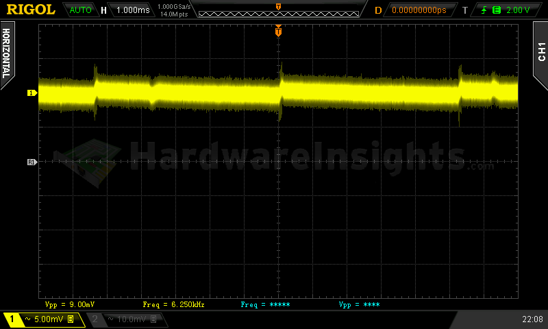
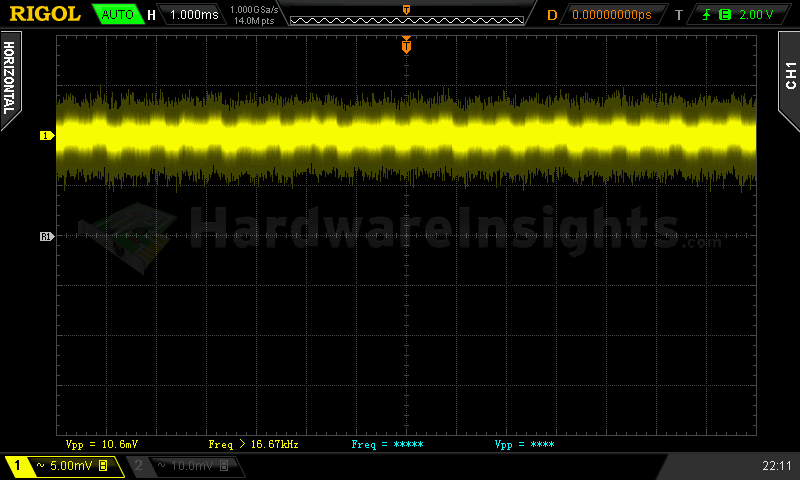

+5 V SB ripple (left to right): 0 A; 2.95 A; 3.48 A
Voltage hold-up time
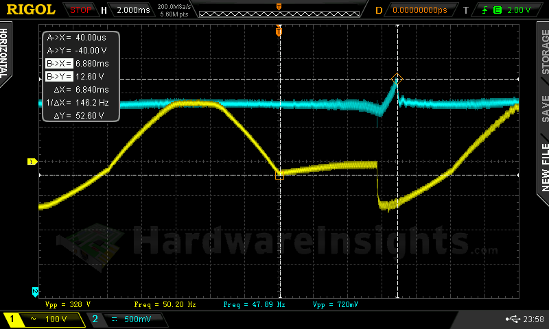
As we can see on the oscilloscope screenshot, the hold-up time of the +12 V rail is quite short, only 10 ms. And that is not the worst.
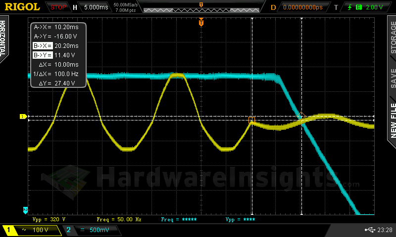
The power good signal hold-up time is very long, 19.3 ms. Why is this when voltage hold-up time is so short? This is in violation of the ATX specification as the power good signal must drop out first, then the voltage. Otherwise the components will be told to stay on while they are not provided with sufficient operating voltage, and their current draw can ostensibly rise to a very high level in order to compensate. This is especially the case of DC–DC VRM designs, and hard drive motor regulators will suffer greatly.
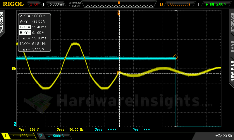
But the problem is even deeper. When interrupting the power for 10 ms, very high voltage spikes appeared when the power was restored. This is also in violation of ATX spec and to stay within the spec, I had to further reduce the time to only 6.84 ms! This is too serious for me to allow this power supply to pass. This is clearly a platform problem as the very same behaviour has been observed by fellow reviewer Aris at Tom’s hardware. Not only for this unit, but also for other units of even different versions of Astro platform.
Combined loading
Combined loading was OK for the Zalman ZM750-EBT. Firstly, let’s talk about the voltage regulation. As this is a synchronously-rectified topology with DC–DC converters, the results are expected to be very good. As we have already established, the +5 V SB regulation could be better, the voltage starts quite high at 5.17 V. It is similar with the +12 and −12 V rails. Basically all the rails showed regulation worse than 2%, so these results reflect more of a mainstream unit rather than a high-end one.
| Output power | Load/ voltage +5 V SB | Load/ voltage +3.3 V | Load/ voltage +5 V | Load/ voltage +12 V | Load/ voltage −12 V | Input power | Efficiency/ power factor |
| 3.6 %/ 27.24 W | 0 A/ 5.17 V | 0 A/ 3.37 V | 0.296/ 5.10 V | 1.838 A/ 12.28 V | 0.285 A/ −11.09 V | 39.36 W | 69.2 %/ 0.733 |
| 20 %/ 144.23 W | 0.553 A/ 5.15 V | 3.15 A/ 3.36 V | 2.225 A/ 5.09 V | 9.47 A/ 12.27 V | 0.291 A/ −11.27 V | 165.5 W | 87.2 %/ 0.976 |
| 40 %/ 305.91 W | 1.06 A/ 5.14 V | 4.09 A/ 3.35 V | 3.37 A/ 5.08 V | 21.74 A/ 12.25 V | 0.290 A/ −11.56 V | 342.0 W | 89.5 %/ 0.991 |
| 60 %/ 459.62 W | 1.58 A/ 5.12 V | 5.52 A/ 3.34 V | 4.88 A/ 5.07 V | 33.1 A/ 12.23 V | 0.299/ −11.86 V | 516.9 W | 88.9 %/ 0.994 |
|
80 %/ 611.83 |
2.91 A/ 5.10 V | 6.98 A/ 3.34 V | 5.99 A/ 5.07 V | 44.2 A/ 12.21 V | 0.304 A/ −12.03 V | 695.1 W | 88.0 %/ 0.996 |
| 100 %/ 743.84 W | 2.90 A/ 5.07 V | 10.7 A/ 3.30 V | 10.37 A/ 5.03 V | 52.3 A/ 12.20 V | 0.301 A/ −12.06 V | 853.5 W | 87.2 %/ 0.997 |
As for the overall efficiency, it dipped under 90%, so once again (and even Aris concurs), this unit is slightly worse than competing 80 PLUS Gold units, even the ones that use the same platform.
Combined loading ripple
Unlike the GVM units, the EBT exhibited very nice ripple values. And even though it occasionally crossed the 40% threshold I have set up for high-end units, overall the results are still good.
| Output % | Ripple +5 V SB | Ripple +3.3 V | Ripple +5 V | Ripple +12 V | Ripple −12 V |
| 3.6 | 19.0 mV | 6.80 mV | 16.4 mV | 18.8 mV | 24.0 mV |
| 20 | 21.8 mV | 7.80 mV | 18.4 mV | 12.4 mV | 24.0 mV |
| 40 | 8.80 mV | 6.60 mV | 16.4 mV | 14.8 mV | 23.2 mV |
| 60 | 14.20 mV | 20.4 mV | 12.8 mV | 19.6 mV | 25.6 mV |
| 80 | 20.0 mV | 22.0 mV | 16.6 mV | 15.4 mV | 15.6 mV |
| 100 | 23.4 mV | 22.8 mV | 19.8 mV | 17.0 mV | 27.2 mV |
Funnily enough, this time the results I’m comparing from Tom’s are quite bad with their unit failing to meet ATX specification. It seems to me that either Zalman units are cursed, or they really have some serious issues with quality control.
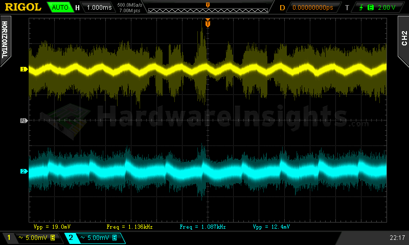
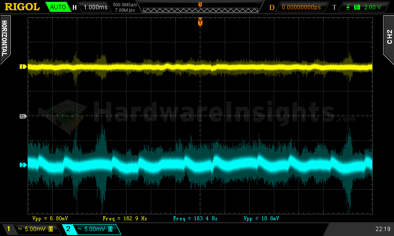
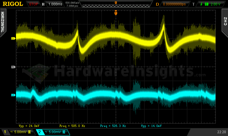
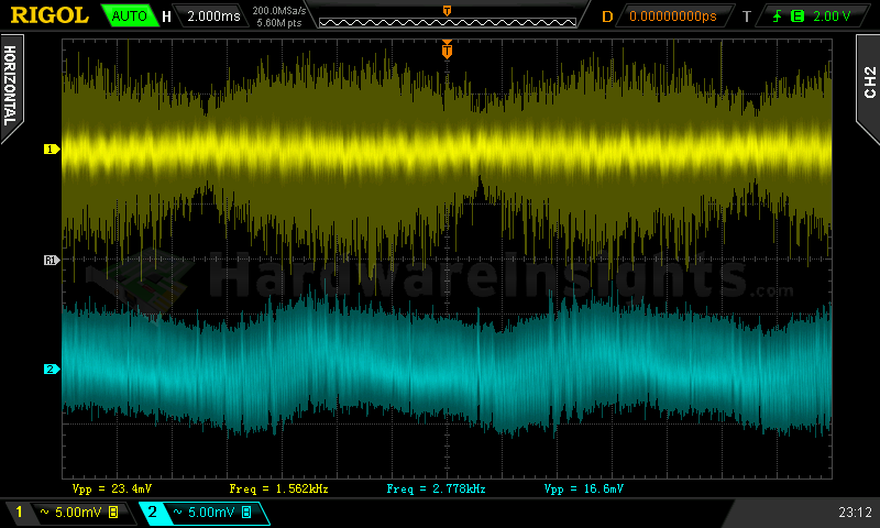
Ripple 3.6% load (left to right): +5 V SB; +3.3 V; +5 V; −12 V. The second channel is connected to +12 V.
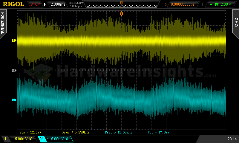
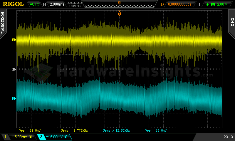
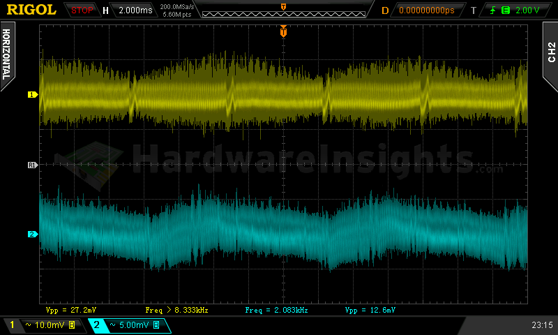
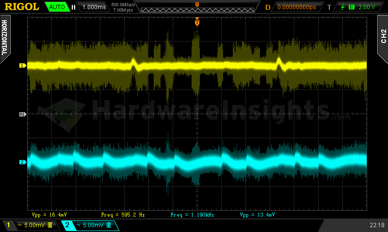
Ripple 100% load (left to right): +5 V SB; +3.3 V; +5 V; −12 V. The second channel is connected to +12 V.
Crossloading, overloading
Crossloading tests went fine, as is expected from a platform utilizing DC-DC converters. The voltage regulation was mostly the same. Efficiency dropped further, even under 80 % with a crossload of the +3.3 V rail. But I’m still a bit apprehensive on passing judgement here since I’m using a new power meter, so let’s give it some more time. Overloading any individual rail was futile. The OTP works, as the unit turned off after 3 minutes of stalling the fan under full load. Under full load the exhaust temperature was over 42 °C and the unit’s fan ran at full speed. But combined overloading was a disaster. After drawing some 850 W an incredibly strong smell started to emanate from the unit, I am not sure whether it was from the the transformer or the primary side, but it definitely wasn’t the secondary as the fan did not spin substantially faster.
| Output power | Load/ voltage +5 V SB | Load/ voltage +3.3 V | Load/ voltage +5 V | Load/ voltage +12 V | Load/ voltage −12 V | Input power | Efficiency/ power factor |
| 14 %/ 105.57 W | 0.545 A/ 5.16 V | 22.8 A/ 3.35 V | 0.266 A/ 5.09 V | 1.822 A/ 12.29 V | 0.274 A/ −11.26 V | 135.7 W | 77.8 %/ 0.970 |
| 18 %/ 138.38 W | 0.557 A/ 5.15 V | 0 A/ 3.35 | 21.7 A/ 5.07 V | 1.814 A/ 12.30 V | 0.282 A/ −11.30 V | 169.5 W | 81.6 %/ 0.973 |
| 98 %/ 735.75 W | 0.570 A/ 5.12 V | 0 A/ 3.33 V | 0.300 A/ 5.07 V | 59.7 A/ 12.19 V | 0.296 A/ −12.05 V | 840.6 W | 87.5 %/ 0.997 |
| 116 %/ 871.93 W | 3.45 A/ 5.06 V | 23.0 A/ 3.30 V | 25.7 A/ 5.03 V | 63.6 A/ 10.16 V | 0.277 A/ −12.10 V | 1260 W | 69.2 %/ 0.997 |
So I was pretty sure that if I let it continue in this manner, it would have exploded. Rather than allowing that to take place, I changed the loading model to see which of the protections do work. I think it’s pretty clear I couldn’t have accomplished that task with a dead unit ![]() So I always turned off the new additional load, increased load on other rails and then turned it on again for a while to see what happens. As the load is applied almost instantly with this new draw (unlike the thermistor-limited halogen bulbs), this more accurately simulates the sudden increased current draw from real computer. But even then the OPP never engaged. There does however seem to be some kind of power limiting on the primary side. The unit did behave ordinarily though when the voltage was constantly lowered with more current being drawn. The unit’s UVP did not engage however even with 10.16 V on the +12 V rail, it did finally turn itself off… but only because it overheated! This is absolutely unacceptable for a high-end unit!
So I always turned off the new additional load, increased load on other rails and then turned it on again for a while to see what happens. As the load is applied almost instantly with this new draw (unlike the thermistor-limited halogen bulbs), this more accurately simulates the sudden increased current draw from real computer. But even then the OPP never engaged. There does however seem to be some kind of power limiting on the primary side. The unit did behave ordinarily though when the voltage was constantly lowered with more current being drawn. The unit’s UVP did not engage however even with 10.16 V on the +12 V rail, it did finally turn itself off… but only because it overheated! This is absolutely unacceptable for a high-end unit!
Crossloading, overloading ripple
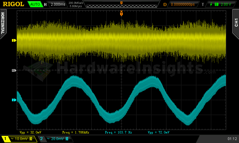
In this limited set of tests, the ripple was even better than that in the combined loading set. However, during overloading 100Hz ripple migrated from the primary to the secondary side! The amplitude also rose significantly. I think we can clearly see that there are some serious problems in the PFC/switching section of the ZM750-EBT despite them even having used relatively large bulk capacitor, which resulted not only in this ripple, but also in the strange behaviour we saw during the hold-up time testing.
| Output % | Ripple +5 V SB | Ripple +3.3 V | Ripple +5 V | Ripple +12 V | Ripple −12 V |
| 14 | 8.60 mV | 4.80 mV | 7.20 mV | 7.60 mV | 21.0 mV |
| 18 | 9.60 mV | 6.56 mV | 7.00 mV | 6.96 mV | 18.0 mV |
| 98 | 17.2 mV | 9.8 mV | 10.4 mV | 15.0 mV | 30.8 mV |
| 116 | 32.0 mV | — | — | 72.0 mV | — |
Fan speed, temperatures and noise
The fan of the ZM750-EBT started spinning right away, but until test five (80 % load) it stayed at just about 700 RPM, and at that speed it was basically inaudible. The noise is just barely above 38.5 dBA ambient. Later on it became noticeably audible, and at full speed it was very noisy.
| Output % | Fan speed (RPM) | Temperature intake/ outtake | Noise (dBA) |
| 3.6 | 703 | 14 °C/ 14 °C | 38.6 |
| 20 | 706 | 15 °C/ 17 °C | 38.6 |
| 40 | 706 | 16 °C/ 19 °C | 38.6 |
| 60 | 715 | 16 °C/ 20 °C | 38.6 |
| 80 | 929 | 17 °C/ 22 °C | 39.1 |
| 100 | 1235 | 18 °C/ 24 °C | 42.2 |
| CL 13 | 709 | 15 °C/ 15 °C | 38.6 |
| CL 18 | 710 | 15 °C/ 21 °C | 38.6 |
| CL 99 | 1016 | 19 °C/ 26 °C | 39.7 |
| OL 116 | 1517 | 21 °C/ 32 °C | 48.5 |
The temperatures were reasonable most of the time, and only during overloading tests was the serious problem of localized overheating exposed. It got so hot it even started to stink as some parts were obviously overheating and melting inside. But not until the secondary heatsink warmed up did it start to spin at full speed. Overall, I would say that this unit seems to run too hot internally for my liking as it also shut down prematurely when its fan was manually seized.

