Contents
- 1Introduction
- 1.1Packaging and accessories
- 2Connectors & cabling
- 2.1Casing & cooling
- 3Input filtering
- 4Primary side
- 4.1+5 V stand-by rail
- 5Secondary side
- 5.1Build quality
- 6Load testing
- 6.1Loading +5 V SB
- 6.2Voltage hold-up time
- 6.3Combined loading
- 6.4Combined loading ripple
- 6.5Crossloading, overloading
- 6.6Crossloading, overloading ripple
- 7Conclusion and evaluation
- 7.1Thanks
- 7.2Discussion
Load testing
Loading +5 V SB
As always, all load testing is done in accordance with testing methodology. I like the voltage regulation, after couple last units where the voltage always sunk with load, this time the Cooler Master G550M holds quite good. On the other hand ripple suppresion is below average. In spec, yes, but 10 mV is nothing special. Efficiency is the same, barely around 70 %.
| Output (W) | Load (A) | Voltage (V)/ ripple (mV) | Input (W) | Efficiency/power factor |
| 0 | 0 | 5.09/6.80 | 1 | —/0.03 |
| 12.10 | 2.41 | 5.02/8.20 | 16.50 | 73.3/0.32 |
| 16.77 | 3.35 | 5.00/8.40 | 23.0 | 72.9/0.4 |
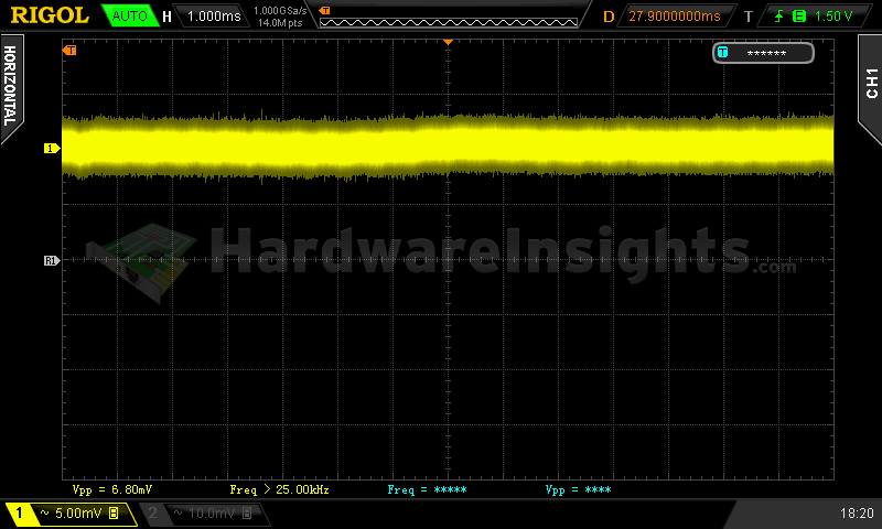
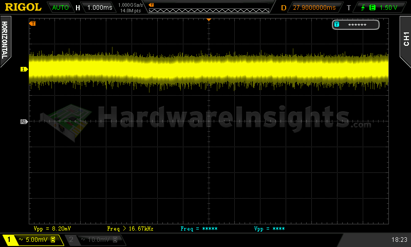
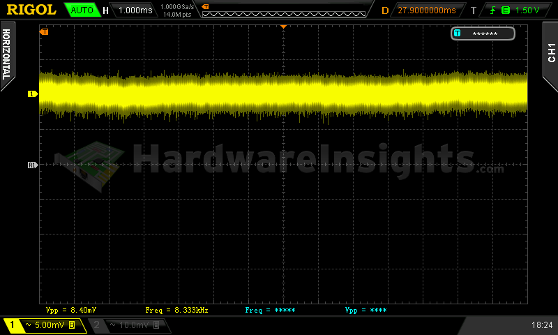
+5 V SB ripple (left to right): 0 A; 2.41 A; 3.35 A
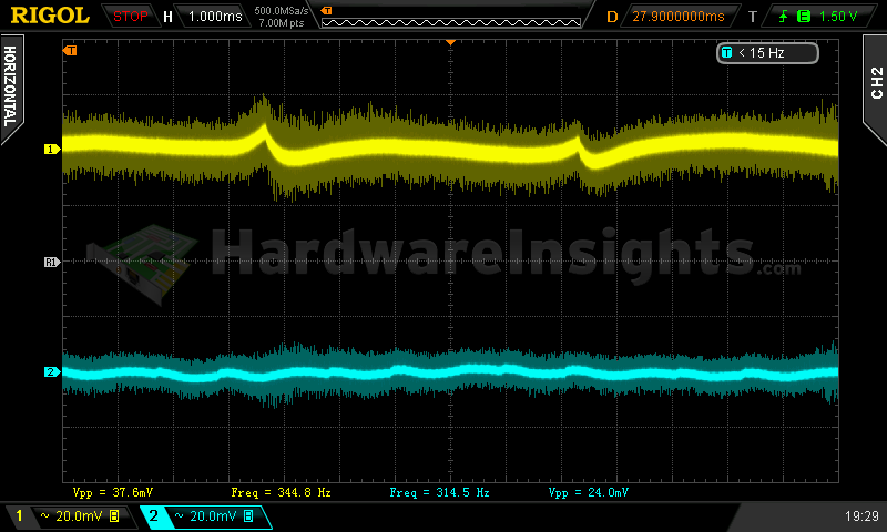
Voltage hold-up time
The hold-up time of the +12 V rail on the scope image is quite good, big input capacitor helps even though the unit has worse efficiency. Almost 30 ms is nice.
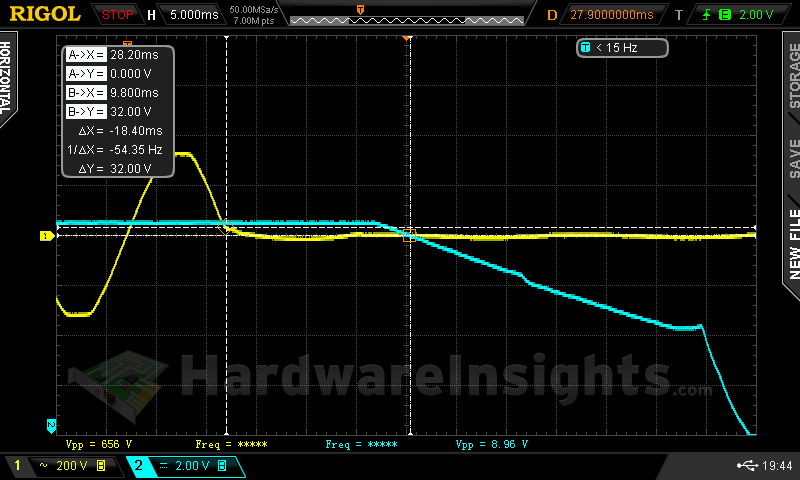
When trying to interrupt the power for this time period, we can see there is a drop around the 11.4 V minimum (maybe slightly lower), after resuming the power the voltage starts oscillating a bit – first it goes up, then down again, than there is transient spike up to 12.68 V which is above tolerance and then it oscillates a few times until slowly returning to previous level.
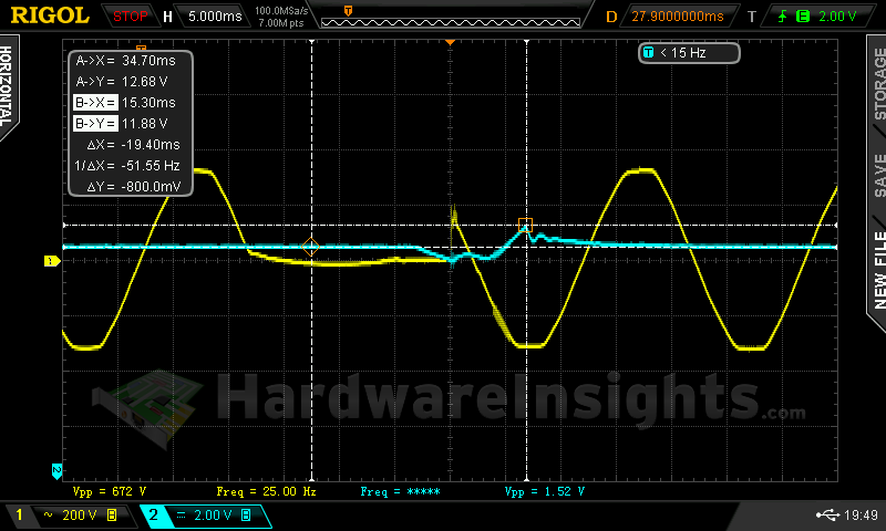
So my estimate (I did not measure it exactly) is somewhere between 20 and 25 ms to fully stay within ATX specification. As always, quality UPS will help especially with bad power grid.
Combined loading
Combined loading was OK for G550M. I am not saying flawless (as I usually do) because the −12 V voltage never reached even the nominal, lowest it went was −11.78 V under full load. The fan profile is set very slow, it was spinning on minimum speed until about 80% load, than under full load it finally run slightly faster which resulted in lower temperature than before. However, temperatures were still very high, especially because of the fact there are no perforations under the AC inlet. So not only there is pocket of hot air on the secondary side, but all the hot air has to pass through primary side perforations and due to overall worse airflow the unit is warmer as a whole. The question is if the profile is even set this way on purpose or it is just poor manufacturing quality – as I previously stated the thermistor barely touches heatsink and I have already seen CWT units where it was several millimeters away from it.
| Output power | Load/ voltage +5 V SB | Load/ voltage +3.3 V | Load/ voltage +5 V | Load/ voltage +12 V | Load/ voltage −12 V | Input power | Efficiency/power factor | Temperature intake/ outtake |
| 4.9 %/ 27.14 W | 0 A/ 5.08 V | 0 A/ 3.39 V | 0.299 A/ 5.06 V | 1.855 A/ 12.06 V | 0.293 A/ −11.14 V | 38.0 W | 71.4 %/ 0.60 | 23 °C/ 26 °C |
| 20 %/ 98.98 W | 0.493 A/ 5.05 V | 1.50 A/ 3.38 V | 1.496 A/ 5.05 V | 7.03 A/ 12.03 V | 0.298A/ −11.25 V | 119.5 W | 82.8 %/ 0.89 | 25 °C/ 29 °C |
| 40 %/ 217.75 W | 0.97 A/ 5.02 V | 3.15 A/ 3.35 V | 3.37 A/ 5.03 V | 15.16 A/ 12.00 V | 0.303 A/ −11.38 V | 231.5 W | 89.4 %/ 0.96 | 26 °C/ 33 °C |
| 60 %/ 325.43 W | 1.44 A/ 4.98 V | 5.95 A/ 3.33 V | 4.84 A/ 5.00 V | 22.6 A/ 11.98 V | 0.307 A/ −11.52 V | 365.0 W | 89.2 %/ 0.98 | 27 °C/ 40 °C |
|
80 %/ 439.04 W |
1.89 A/ 4.93 V | 7.08 A/ 3.31 V | 5.95 A/ 4.98 V | 31.3 A/ 11.92 V | 0.307 A/ −11.68 V | 472.0 W | 87.4 %/ 0.98 | 27 °C/ 47 °C |
| 100 %/ 543.31 W | 2.33 A/ 4.91 V | 8.40 A/ 3.29 V | 7.68 A/ 4.96 V | 38.9 A/ 11.89 V | 0.308 A/ −11.78 V | 597.0 W | 85.6 %/ 0.99 | 27 °C/ 45 °C |
Voltage regulation on +12 V was initially tighter but with increasing load the value dropped to just 11.89 V. Other rails mostly showed the same behaviour, only exception was the +3.3 V which started quite high already (3.39 V or 2.7 % from nominal) and dropped under 3.3 V anyway. It is not really bad for mainstream unit, all the positive rails stayed within 3 %, but considering it is +12V device with DC-DC modules, I would expect better results anyway. Highest efficiency this unit achieved was about 89 % but the lowest (at certification point of 20% load) was just over 82 % so this unit really could not get 80 PLUS Silver certificate and the Bronze one is valid. With minimum load it was poor, just over 70 %.
Combined loading ripple
The ripple suppression of Cooler Master G550M is quite nice on both ±12V rails, however the stand-by rail and the +5 V rail are somewhat worse, over 60 % of the allowed maximum of 50 mV even though there are quite substantial capacitances on both rails. This could be lower and also there is high probability the capacitors will fail soon with their poor quality and the unit’s high temperature so then the ripple will get even worse.
| Output % | Ripple +5 V SB | Ripple +3.3 V | Ripple +5 V | Ripple +12 V | Ripple −12 V |
| 4.9 | 20.5 mV | 15.2 mV | 23.2 mV | 31.2 mV | 29.6 mV |
| 20 | 32.8 mV | 19.2 mV | 28.0 mV | 25.6 mV | 25.6 mV |
| 40 | 32.8 mV | 24.4 mV | 28.8 mV | 26.4 mV | 33.6 mV |
| 60 | 24.0 mV | 21.6 mV | 19.2 mV | 22.4 mV | 33.6 mV |
| 80 | 21.6 mV | 22.4 mV | 27.2 mV | 25.6 mV | 28.8 mV |
| 100 | 31.2 mV | 24.0 mV | 32.8 mV | 28.0 mV | 37.6 mV |
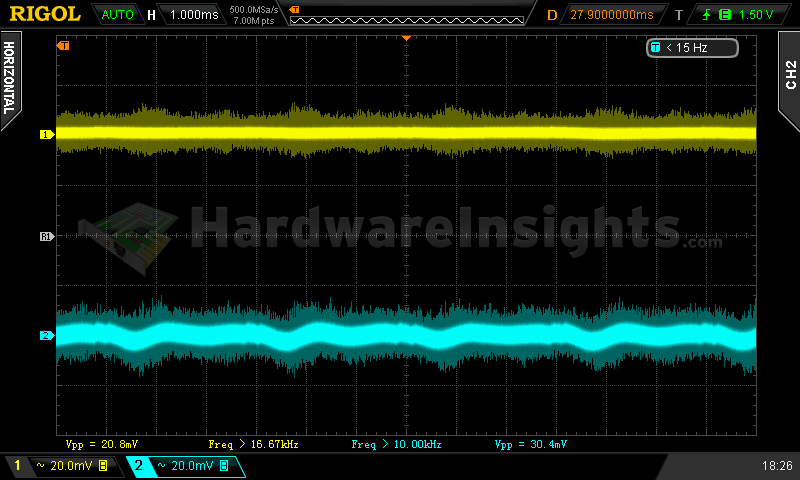
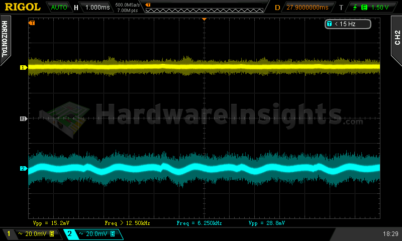
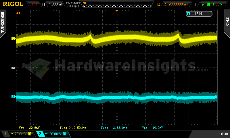
Ripple 4.9% load (left to right): +5 V SB; +3.3 V; +5 V; −12 V. The second channel is connected to +12 V.
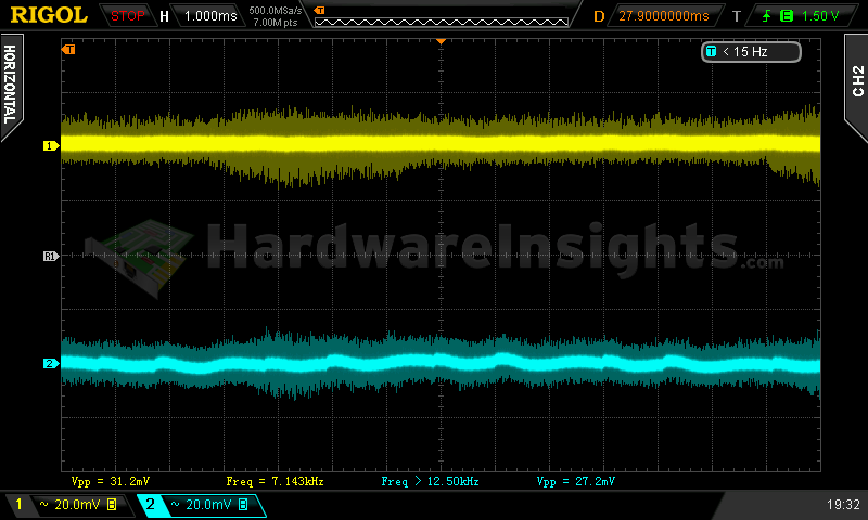
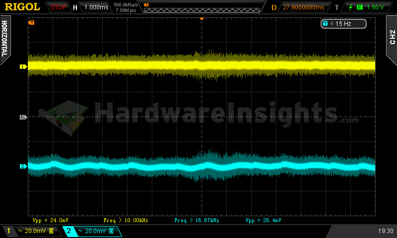
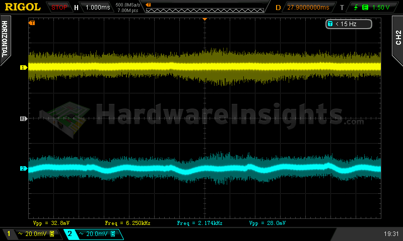
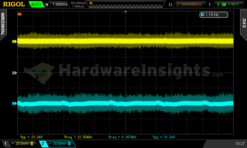
Ripple 100% load (left to right): +5 V SB; +3.3 V; +5 V; −12 V. The second channel is connected to +12 V.
Crossloading, overloading
Crossloading went fine but considering this unit has DC-DC modules, I did not really expect anything else. Voltages dropped here and there but nothing really bad. Temperatures were still high with high load, also efficiency was quite poor especially when crossloading the +3.3 V rail – I think for that it is time to remove half a point. OCP on this rail did not react to my maximum load, +5V OCP turned the unit off above 23.5 A.
| Output power | Load/ voltage +5 V SB | Load/ voltage +3.3 V | Load/ voltage +5 V | Load/ voltage +12 V | Load/ voltage −12 V | Input power | Efficiency/power factor | Temperature intake/ outtake |
| 100 %/ 548.73 W | 0.482 A/ 4.97 V | 1.45 A/ 3.31 V | 1.500 A/ 4.99 V | 44.8 A/ 11.86 V | 0.306 A/ −11.78 V | 636.5 W | 86.2 %/ 0.99 | 28 °C/ 43 °C |
| 18 %/ 101.68 W | 0.493 A/ 5.02 V | 19.85 A/ 3.33 V | 1.475 A/ 5.01 V | 1.858 A/ 12.03 V | 0.297 A/ −11.35 V | 132.0 W | 77.0 %/ 0.90 | 26 °C/ 36 °C |
| 24 %/ 132.58 W | 0.489 A/ 5.02 V | 1.48 A/ 3.34 V | 19.75 A/ 5.02 V | 1.877 A/ 12.03 V | 0.304 A/ −11.35 V | 162.5 W | 81.6 %/ 0.93 | 26 °C/ 35 °C |
| 129 %/ 708.88 W | 3.16 A/ 4.84 V | 11.85 A/ 3.23 V | 11.83 A/ 4.92 V | 50.2 A/ 11.82 V | 0.313 A/ −11.91 V | 824.5 W | 86.0 %/ 0.99 | 27 °C/ 45 °C |
Because of the high temperatures and clearly slow fan profile (plus low efficiency), I have been curious about the result of the Sweater contest. My estimate was right, the unit overheated after five minutes. I must admit it was slightly overloaded as I forgot some load on +5 V rail but it would just take couple more minutes. So while the OTP is working, the units fan controller seems to not increase the speed much even with very high temperatures – it seems to be fixed to low speeds. Combined overloading went OK even though voltages were sinking even lower. Judging from the fact it did not want to turn on for a while after shutting down, it seems the OTP was the reason why it shut down – the G550M overheated again.
Crossloading, overloading ripple
The ripple stayed mostly on the same levels as under combined loading, but during overload it went over 50 mV on both +12 V and +5 V SB rails.
| Output % | Ripple +5 V SB | Ripple +3.3 V | Ripple +5 V | Ripple +12 V | Ripple −12 V |
| 100 | 31.2 mV | 25.6 mV | 33.6 mV | 33.6 mV | 36.0 mV |
| 18 | 32.0 mV | 29.6 mV | 28.0 mV | 21.6 mV | 27.2 mV |
| 24 | 36.0 mV | 32.0 mV | 33.6 mV | 25.6 mV | 34.4 mV |
| 129 | 56.0 mV | — | — | 57.6 mV | — |

