Contents
- 1Introducing the Cooler Master V650
- 1.1Packaging and accessories
- 2Connectors & cabling
- 2.1Casing & cooling
- 3Input filtering
- 4Primary side
- 4.1+5 V stand-by rail
- 5Secondary side
- 5.1Build quality
- 6Load testing
- 6.1Loading +5 V SB
- 6.2Hold-up time
- 6.3Combined loading
- 6.4Combined loading ripple
- 6.5Crossloading, overloading
- 6.6Crossloading, overloading ripple
- 6.7Fan speed, temperatures and noise
- 7Conclusion and evaluation
- 7.1Thanks
- 7.2Discussion
Input filtering
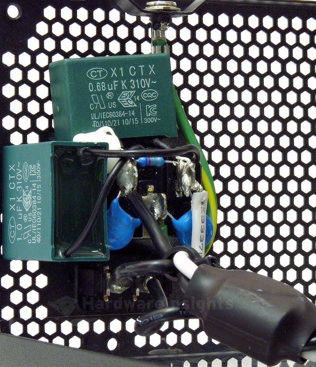
The input filtering begins with its first stage situated directly on the input receptacle. We can see two film X capacitors and two ceramic Y capacitors. Notice the bleeder resistor across phase and neutral. The cables running to the main board also go through a ferrite core choke.
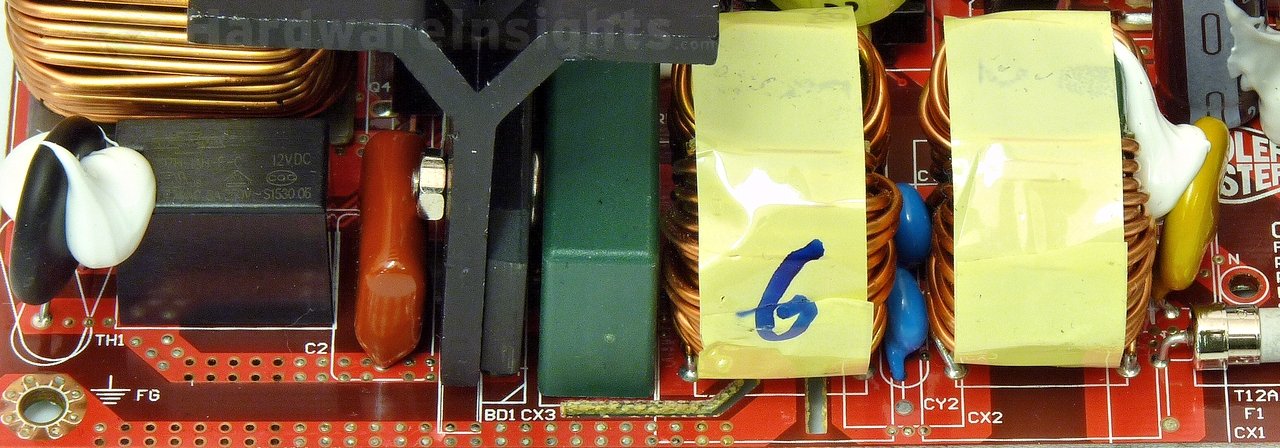
If we move on to the main board, we can see that there are two more Y capacitors (plus a fifth one between the primary and secondary sides). There is also one more X capacitor, two common mode chokes and a varistor (without heatshrink sleeving). On the very left side you can see a relay bypass for the thermistor (also without heatshrink). This part of the board was unpopulated in the V550S.
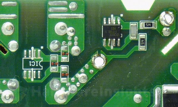
Enhance also put the Champion Micro CM02X microchip to discharge the X capacitors only upon power interruption. The good thing is that it is connected directly to the input, before the fuse. So in all cases it will discharge the capacitors which might otherwise cause bodily harm to an unsuspecting victim. On the other hand I do not understand at all why there is a bleeder resistor on the input receptacle which serves no other purpose in our case other than to add to a loss of efficiency.
The X capacitors (between the live and neutral) and Y capacitors (between live and ground/neutral and ground) are used to filter out high-frequency ripple that emanates from the power grid. That is the noise of which manifests in the form of feedback from electronic devices which lack adequate filtering due to cost cutting. But also from devices where filtering was very difficult to implement (powerful devices, e.g. microwave ovens). It also prevents ripple from this unit itself from feeding back into the grid.
Chokes are used for the same reason, and together with the X/Y capacitors they form an input filter. Such filters are often made as one component, they may also be integrated together with AC receptacle. These components may also (partially) help to filter smaller voltage spikes in the power grid. To suppress more serious spikes (for example from distant lightning strikes hitting the power grid), the MOV (metal-oxide varistor) is used. Thermistor is then used to suppress current spikes when first connecting the unit to power (i.e. flipping the power switch).
The Y capacitors are also often situated between the high-voltage primary and the low-voltage secondary sides. These days, more Y capacitors are used even between primary common (ground after an input rectifier) and earth ground to suppress internal interference and keep it from getting to the secondary side. It is because really high-frequency ripple goes everywhere it can to some extent (including coupling through the insulation, metal casing etc…). That is also why the AC wires themselves are often inserted through the ferrite toroid inductor (to suppress such coupling).

