Contents
- 1Introducing the Corsair HX750i
- 1.1Packaging and accessories
- 2Connectors & cabling
- 2.1Casing & cooling
- 3Input filtering
- 4Primary side
- 4.1+5 V stand-by rail
- 5Secondary side
- 5.1Build quality
- 6Load testing
- 6.1Loading +5 V SB
- 6.2Hold-up time
- 6.3Combined loading
- 6.4Combined loading ripple
- 6.5Crossloading, overloading
- 6.6Crossloading, overloading ripple
- 6.7Fan speed, temperatures and noise
- 7The Link
- 7.1The application
- 8Conclusion and evaluation
- 8.1Thanks
- 8.2Discussion
Secondary side
There are two groups consisting of 3 transistors each for rectification. This time they are Infineon BSC014N04LS (100/400 A at 40 V and 25 °C, RDS(On) 1.9 mΩ at 50 A and VGS of 4.5 V or 1.4 mΩ at 10 V) in PG-TDSON-8 FL package. It is just another slightly different version of HSON, LFPAK, DFN5x6-8 etc. The Texas Instruments UCC27324D low-side driver is used to control the transistors. Thick metal plates are used as conductors for the current to and from the main board. On the board itself, the paths are reinforced by metal plates which has been first screwed by a few small screws and then soldered. On the boards themselves, there are small metal plates acting as heatsinks. Also one taller plate is soldered directly on the +12 V path to act as heatsink as well, in the middle of the filtering capacitors. Those are Chemi-Con KZH 3300/16 (D12.5); there are also vacant spots for two polymers.
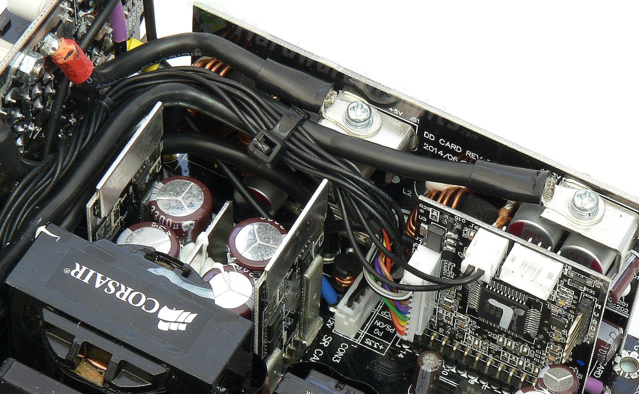
In the corner of the board, connected by three resistor current shunts (in parallel), there is the actual output for the +12 V rail. It has an extra Enesol Enecap 470/16 polymer for filtering. One third of the modular board is directly soldered in here, the other two thirds get power through a pair of thick wires. On each such connections, there are resistor shunts so there is indeed multi-rail OCP functionality. But the DC-DC board is soldered directly in the rectified +12 V before the shunts (so there is indeed no direct limiting for +3.3 and +5 V combined power). It is the same as within the RM550x, consisting of three Ubiq QM3004D (55/110 A at 30 V and 25 °C, 8.5 mΩ at 30 A and with VGS of 10 V or 14 mΩ at 15 A and 4.5 V) transistor for each converter. Both are driven by the usual Anpec APW7159. The modules have one more Enesol 470/16 polymer and two 1500/6.3 for output filtering (each). The conductors leading to the modular board are screwed onto metal plates in here.
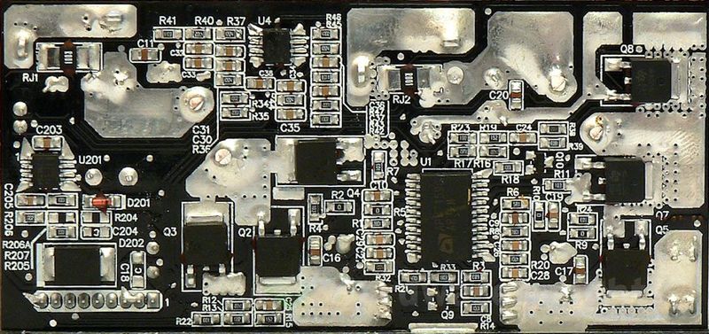
A Texas Instruments buck controller, the TPS5430, seems to provide stable −12 V output. There is a Chemi-Con KY 1000/16 capacitor to filter the output. The fan controller uses no apparent thermistor sensor. This time the “MCU board” is more advanced as it not only controls the fan, but also reads all the data about the unit and provides digital interconnections. It carries more powerful, 32-bit Microchip PIC32MX250F128D microprocessor. The modular board is filled with Apaq polymers. These tend to go kaboom under some specific heavy duty conditions. But here they should not see such stress, that is also the reason why they have been selected. There is a single AV series 100/16 for −12 V, couple CV 820/6.3 and PV 560/6.3 for the minor rails. The rest, consisting of PV 330/16, is for the additional +12 V filtering.
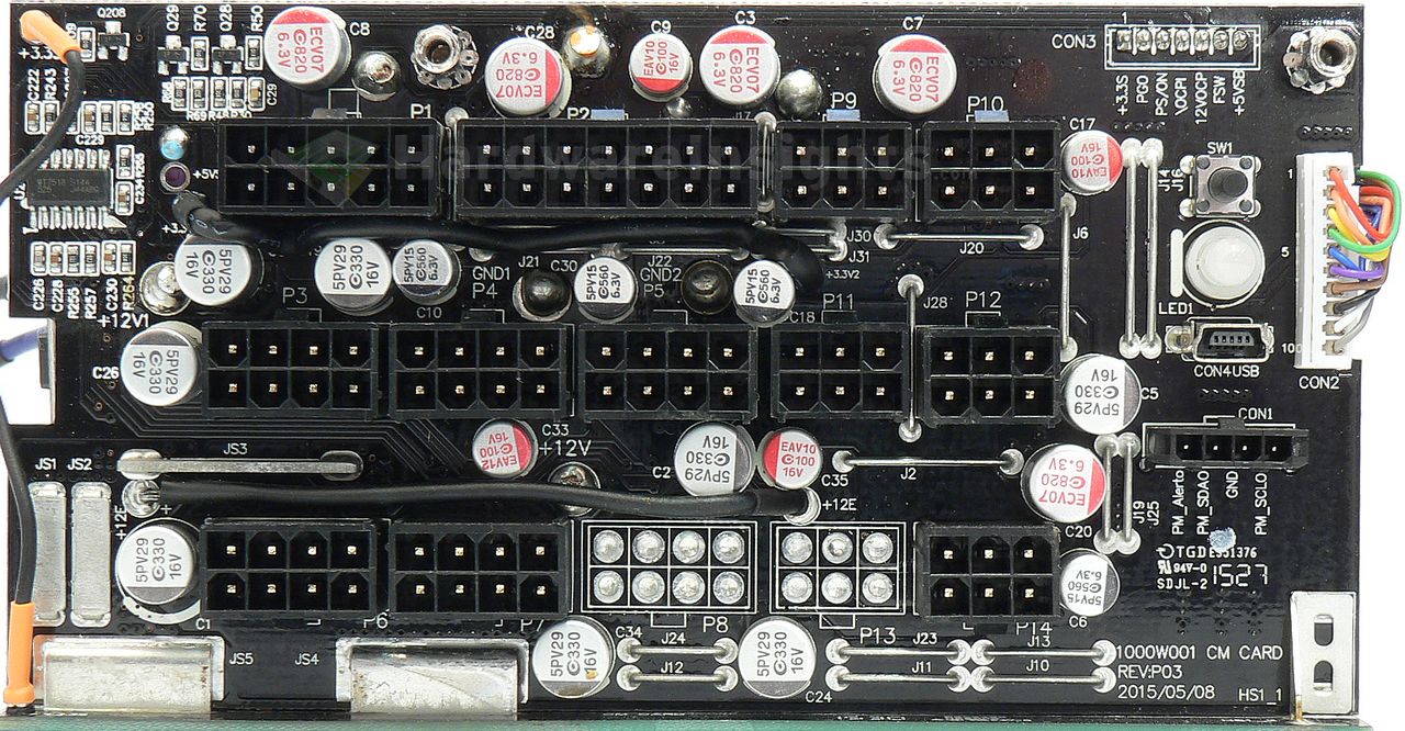
Then there is another QM3004D transistor which seems to supply the +5 V SB output from the +5 V rail when it is running (power supply is on) to save some power (stand-by supply efficiency is slightly worse). For that purpose there is one more 820/6.3 polymer on the +5 V rail. Plus there are two Weltrend WT7518 quad-channel over-current protection monitors, giving 8 channels in total for the +12V rails. Six are for the EPS connectors (in this case only 5 are used), single for the peripherals (through 6-pin PCIe connectors), one for Main ATX. And there is also the WT7502 on the main board for the usual stuff (UVP, OVP, PG, PWR On).
Build quality
As usual, I’ll focus on the overall build quality and other things like electrical safety here, as the quality of the components that were used was already discussed before. The separation between the primary and secondary sides is good, and we also have some extra “teeth” to suppress high-voltages discharges under one of the input filtering coils. The varistor is sleeved with heatshrink, thermistor is not, but it is relay-bypassed so it will see minimum usage. The design is nice and clean, also the wave soldering is very clean on all rails. On the main board there is one manually-resoldered joint, but then the cables to the modular board are soldered manually. This part is quite messy as it has not been cleaned afterwards.
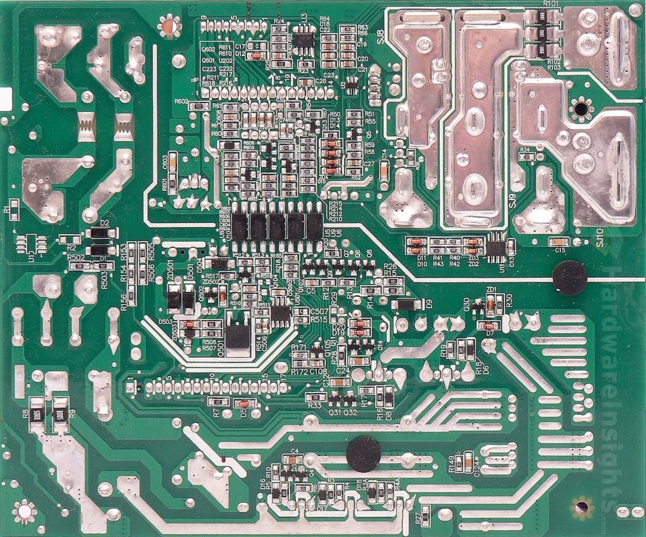
Rather large quantities of silicone have been used to fix the components in place, especially in the input filtering section. Electrodes are precisely trimmed, however, one of such trimmed electrodes somehow managed to get onto the silicone of one of the DC-DC board coils where it was sitting. It is rather a large piece which could have gotten loose in time and short something. On the other hand I found no solder balls. Conductive paths are reinforced by a layer of solder as well as some copper plates. Also all the wire jumpers are quite thick. Overall I’ll deduct 6 points.

