Contents
- 1Power supply testing instruments and methodology introduction
- 1.1History
- 1.2The Load Tester
- 1.3Power interrupter
- 1.4Future possible upgrades
- 2Other equipment
- 2.1Isolation transformer
- 2.2Anechoic chamber
- 3Measuring instruments (electrical values)
- 4Measuring instruments (non-electrical values)
- 4.1Measuring methodology/procedure
Power supply testing instruments and methodology introduction
To avoid constant repetition of the same texts, here is a sum of all the information about how we test power supplies, what equipment, instruments and methodology we use for that. This article will be updated if there is any change in the instruments and methodology. The current version is 1.70.
History
(-): pilot article, Eurocase ATX-350W after rebuilt; basic version if the loading tester without support construction, cooling fans, decoupling capacitors and oscilloscope limiter
(-): Supermicro PWS-502-PQ; decoupling capacitors
(-): Corsair VS450; O-scope limiting
1.0: Evolve Pulse 80+ 500 W; measuring ripple directly on decoupling capacitors
1.1: 0.1 μF ceramic + 10 μF aluminum low-ESR capacitor
1.2: Fractal Design Tesla R2 500 W; measuring voltage directly on the ATX connector
1.25: 2 kVA transformer for pro galvanic separation
1.33: Huntkey FX500SE; Rigol DS2072 O-scope instead of DS1062CA, adding connectors to the load
1.43: Seasonic G-550; UNI-T UT210E clamp meter instead of UT203
1.50: Silverstone SST-ST45SF-G; multimeter FK Technics FK64L instead FK8400, SATA terminators
1.51: Antec VPF450: testing over-temperature protection (obstructing fan grill with a sheet of paper)
1.52: Enermax Digifanless 550 W: The Sweater contest
1.60: Cooler Master V Semi Modular V550S: power interrupter
1.62: Corsair RM550x: laser tachometer
1.70: Super Flower Leadex Platinum 750 W: UNI-T UTE1010A power meter, dual channel thermometer, sound level meter (+anechoic chamber)
1.72: Corsair SF600: UNI-T UT61E digital voltmeter
The Load Tester
Other than maybe a camera, the most important requirement of anything which even thinks to call itself a power supply review is an artificial load capable of drawing at least 100 % of the rated power from the PSU output. I use 20-50W halogen light bulbs for this purpose so the maximum +12V power draw is 650 W in 13 sockets. The other rails can do with loading resistors thanks to their low power nowadays. The −12V rail is loaded with a Papst high-power fan plugged on potential difference between +5 and −12 V.
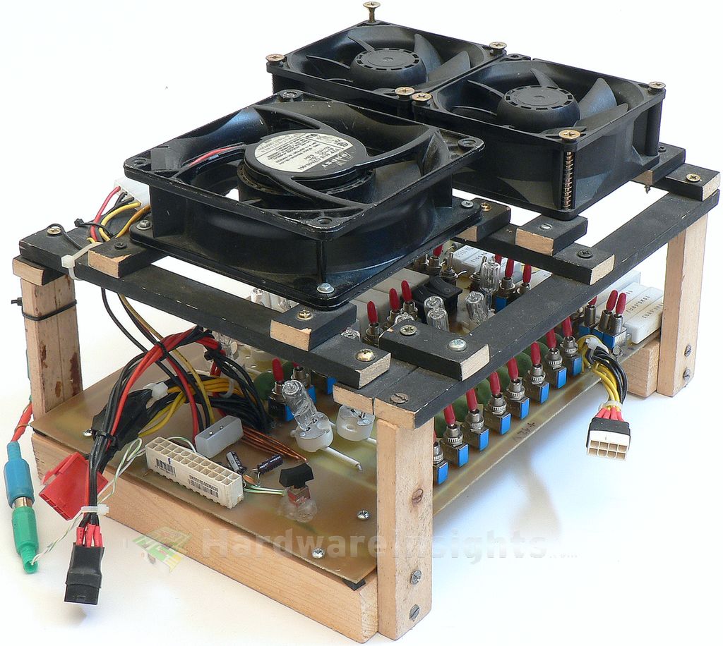
Power supply loader, version 1.0b
Cooling
- Papst 4112 GXMS-061 (120 mm) on potential difference between +5 and −12 V (+resistor to decrease current to approx. 0.3 and 0.2 A)
- 2× Sanyo Denki (Sun Ace 92) 9G0912G104 (92 × 92 × 38 mm, 5000 RPM, 186 m3/h each)
Power connectors
- 1× Main ATX (24pin)
- 1× EPS 12 V (8pin)
- 2× PCIe (6pin)
- 1× PCIe (8pin)
- 1× peripheral molex
Ripple
The load tester is equipped with pair of capacitors for each rail, 0.1μF ceramics and 10μF low-ESR electrolytic capacitor. Intel suggests tantalum capacitor, I chose 22μF one initially because it was closer ESR-wise to tantalum capacitor, that was lately changed to 10μF low-ESR aluminum electrolytic cap. This combination of capacitors simulates the effect of the motherboard when it filters out some of the ripple. This ripple still exists, the oscilloscope just does not see it. It is a mistake not to use them, because we want to measure compliance with ATX specification, and it specifies this, not absolute amount of ripple present.
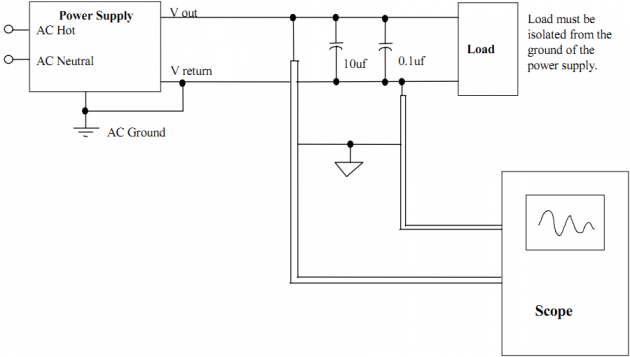
Unfortunately, it is not clear where exactly to plug O-scope probes in the Intel specification and I have experimentally found that it can make a huge difference (as the decoupling effect decreases the further you are from the capacitors), can be up to tens of percent difference. Since the Evolve power supply review, I am trying to measure directly on the capacitors, which required some adjustments as I did not count with this when I was building the loader. But it is doable.
Another thing Intel does not mention and which was again observed in real world is picking up interference on free connectors, behaving like antennas. Usually there is interference from the unit itself (mostly higher harmonics) but also from power grid and this can reach up to tens of MHz, which the O-scope will detect and it is basically indistinguishable from higher harmonics, which the power supply pumps into its output (and we want to measure). For that reason, the ATX spec also specifies to use 20MHz O-scope limiter, but even then you can pick up some of this interference.
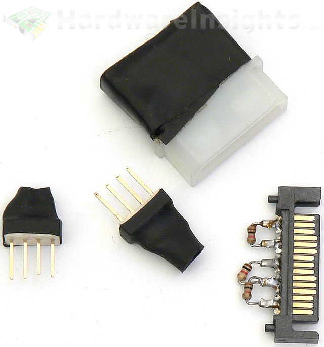
For that reason, over-rippled grounds I have seen earlier were not so much the problem of the PSU itself rather than just by the free cables (not connected anywhere) behaving like antennas. I have experimentally tested the possibility of suppressing this effect by using resistor terminators with 1 kΩ resistors connected to as many of the free connectors as possible. At the moment, I have terminators Molex connectors, Berg connectors and SATA connectors.
As for now, I not only have slightly different decoupling capacitors, but also probes itself used for measuring ripple. Intel suggests differential probes, however, in reality these are rarely used over passive probes as the differences for these frequencies (up to 20 MHz) are not so dramatic. But they exist.
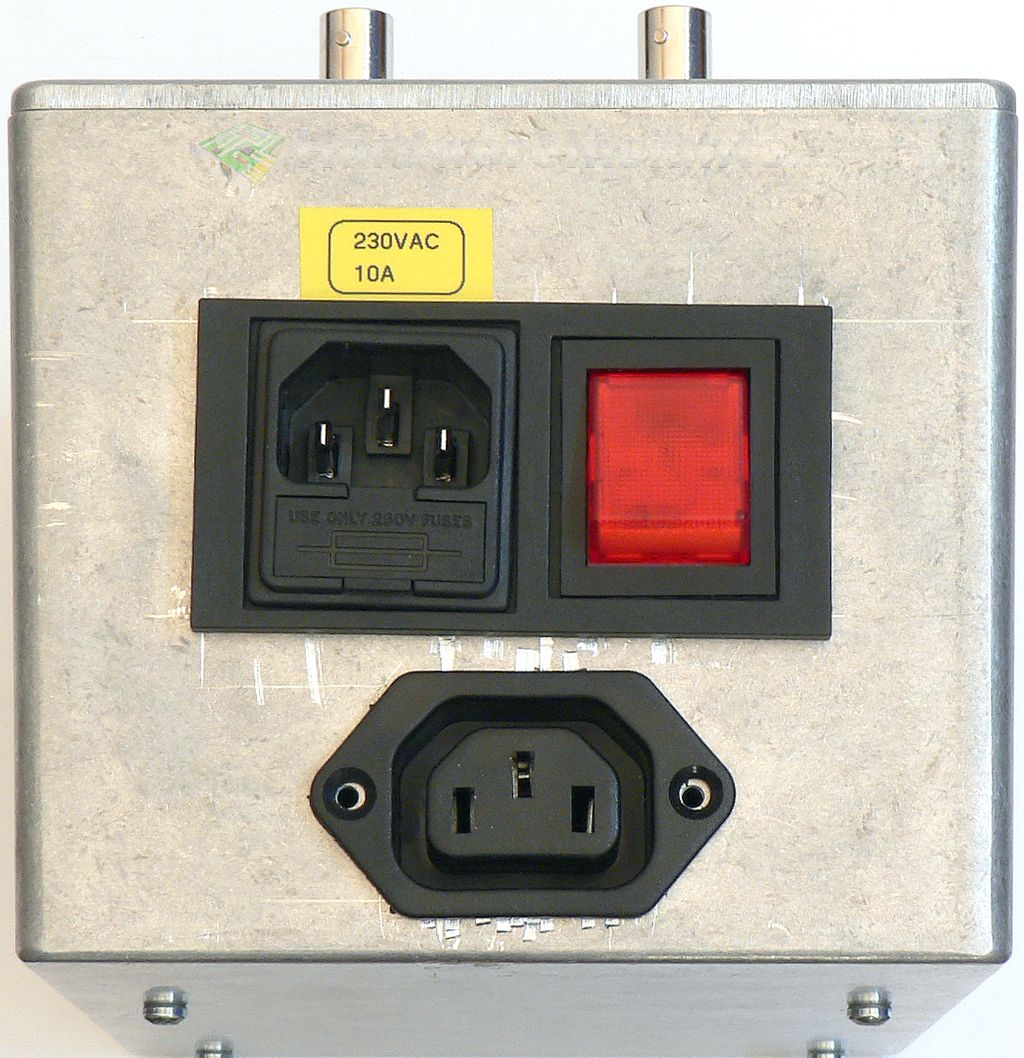
Power interrupter
Since version 1.6 I have a power interrupter capable of handling current of 10 A flowing through it. It is custom-made device from slovakian engineer Matej Svantner (you can contact him at matej[@]svantner.net if you need something similar) in a nice aluminium enclosure which is capable of interrupting the wall power for designated time (with steps of 0.1 ms). It measures 0 V in the grid to start from this point and has a trigger output which may be used as an external oscilloscope trigger to make the O-scope pause (so I can see what is happening).
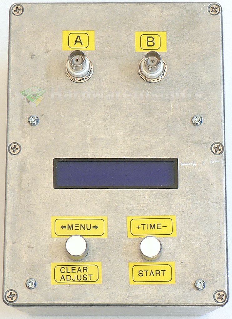
It has an input for external button to start the trigger. However, it does not have a point to connect high-voltage probe so I made myself my own from C13-C14 cable. It looks terrible and would probably cause a headache to safety technician, but it works ☺ The reason for using this interrupter is to measure hold-up time.
Future possible upgrades
Another possibilities to improve measuring accuracy I will try to attend to in future:
- Extra input filtration plugged before the PSU measured
- Extra O-scope probe shielding/multiple shielded probe, or
- Using differential probe
- Shielding the load
- Shielding the PSU measured

