Contents
- 1Introducing the Whitenergy ATX-350W
- 1.1Packaging and accessories
- 2Connectors & cabling
- 2.1Casing & cooling
- 3Input filtering
- 4Primary side
- 4.1+5 V stand-by rail
- 5Secondary side
- 5.1Build quality
- 6Load testing
- 6.1Loading +5 V SB
- 6.2Voltage hold-up time
- 6.3Combined loading
- 6.4Combined loading ripple
- 6.5Crossloading, overloading
- 6.6Crossloading, overloading ripple
- 6.7Fan speed, temperatures and noise
- 7Conclusion and evaluation
- 7.1Discussion
Input filtering
First stage of the input filter inside the ATX-350W unit starts on a board soldered to the input receptacle. The inlet itself is poorly made out of some pressed pieces of metal, not sure whether this will be even safe in the long run (LongRunner has had such an inlet arc). There is an actual X2 film capacitor (0.22μF) and common mode choke on the board. The cap lacks any kind of mechanism to discharge, however, according to norms available to me at this moment, as it is under 0.5 μF, it does not require any discharging resistor.
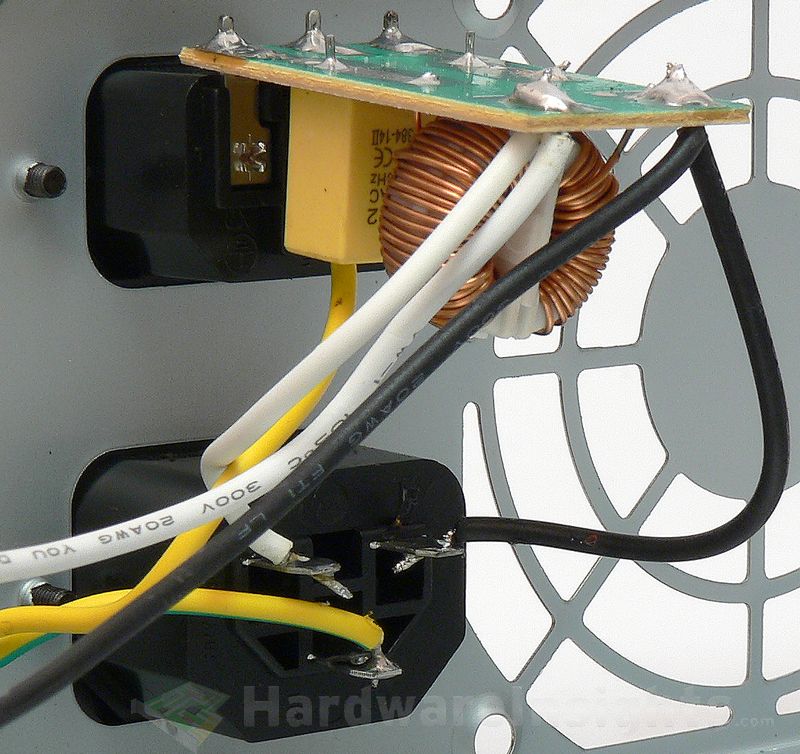
But I do not consider that safe, being directly on the receptacle, somebody can still get shocked. For example when the fuse burns and he sticks fingers in the receptacle right after unplugging the power cord.
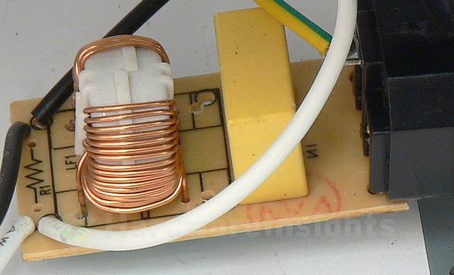
Second stage of the filtering in the ATX-350W is… …missing! Must have been stolen by aliens or something. You can already see solder balls even here on this side of the board…there is a tiny thermistor, but no varistor whatsoever.
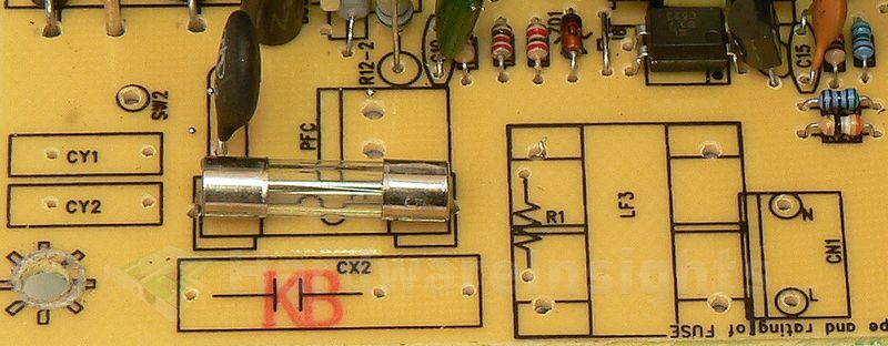
The X capacitors (between the live and neutral) and Y capacitors (between live and ground/neutral and ground) are used to filter out high-frequency ripple that emanates from the power grid. That is the noise of which manifests in the form of feedback from electronic devices which lack adequate filtering due to cost cutting. But also from devices where filtering was very difficult to implement (powerful devices, e.g. microwave ovens). It also prevents ripple from the unit itself from feeding back into the grid.
Chokes are used for the same reason, and together with the X/Y capacitors they form an input filter. Such filters are often made as one component, they may also be integrated together with AC receptacle. These components may also (partially) help to filter smaller voltage spikes in the power grid. To suppress more serious spikes (for example from distant lightning strikes hitting the power grid), the MOV (metal-oxide varistor) is used. Thermistor is then used to suppress current spikes when first connecting the unit to power (i.e. flipping the power switch).
The Y capacitors are also often situated between the high-voltage primary and the low-voltage secondary sides. These days, more Y capacitors are used even between primary common (ground after an input rectifier) and earth ground to suppress internal interference and keep it from getting to the secondary side. It is because really high-frequency ripple goes everywhere it can to some extent (including coupling through the insulation, metal casing etc…). That is also why the AC wires themselves are often inserted through the ferrite toroid inductor (to suppress such coupling).

