Contents
- 1Introducing the Whitenergy ATX-350W
- 1.1Packaging and accessories
- 2Connectors & cabling
- 2.1Casing & cooling
- 3Input filtering
- 4Primary side
- 4.1+5 V stand-by rail
- 5Secondary side
- 5.1Build quality
- 6Load testing
- 6.1Loading +5 V SB
- 6.2Voltage hold-up time
- 6.3Combined loading
- 6.4Combined loading ripple
- 6.5Crossloading, overloading
- 6.6Crossloading, overloading ripple
- 6.7Fan speed, temperatures and noise
- 7Conclusion and evaluation
- 7.1Discussion
Secondary side
Both the +3.3 and +5 V are rectified by Silan Microelectronics SBD20C45T (20/150 A at 45 V and 100 °C, drop of 0.65 V at 10 A and 25 °C) Schottky rectifier in TO-220 package. The +3.3 V rail is derived from +5 V using magamp circuit. Even in 2016 they put only superfast rectifier on the +12 V rail in this ATX-350W unit. It is the SFR16S20T (16/100 A at 200 V and 150 °C, drop of 1.25 V at 8 A and 25 °C) in TO-220, also from Silan. The efficiency of this thing will be tragic. And look at those tiny coils! All the silicon is mounted to the same paper thin heatsink which reminds of the Tower of Pisa.
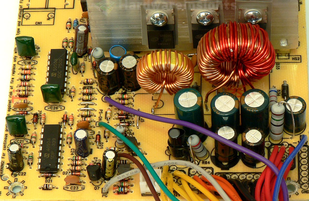
There are more garbage capacitors of very low capacities. The only rail having true Pi filter is the +3.3 V. Like all these Leadman and Leadman copies since the beginning of time, it only has single 1000μF capacitor on the +12 V rail. Just that, one cap, no coil. I think this junk will drop out of ATX spec on ripple suppression even before it explodes. There is no fan control, it spins on full speed being fed directly from +12 V. Only having the LM339, I would wonder if this thing even got working OVP, I think the best we can get is short-circuit protection. Maybe. I take UVP as non-working already. I am not even sure if I should test SCP on all rails first, if it blows right away, we lose all the fun. If I don’t, it will blow up later and I won’t be able to test it. Difficult choice…
Build quality
As usual, I’ll focus on the overall build quality and other things like electrical safety here, as the quality of the components that were used was already discussed before. The separation between the primary and secondary sides is not that good, part of the input side gets too close to the secondary. The heatsinks are not grounded and who knows what’s the quality of the silicone insulation pads, there may be some leakage voltage on them. They are also soldered only to tiny pads which may get torn off the board and they will be even less stable. Also the primary heatsink almost touches one rectifier. The PCB itself is thin and there is no insulation film beneath it. I am not sure if this is necessary according to some norms, if you know something about that let me know. There is that plastic knob to keep the board from touching the metal casing, but I have seen them melt from the heat of the transformer (as it is right next to it).
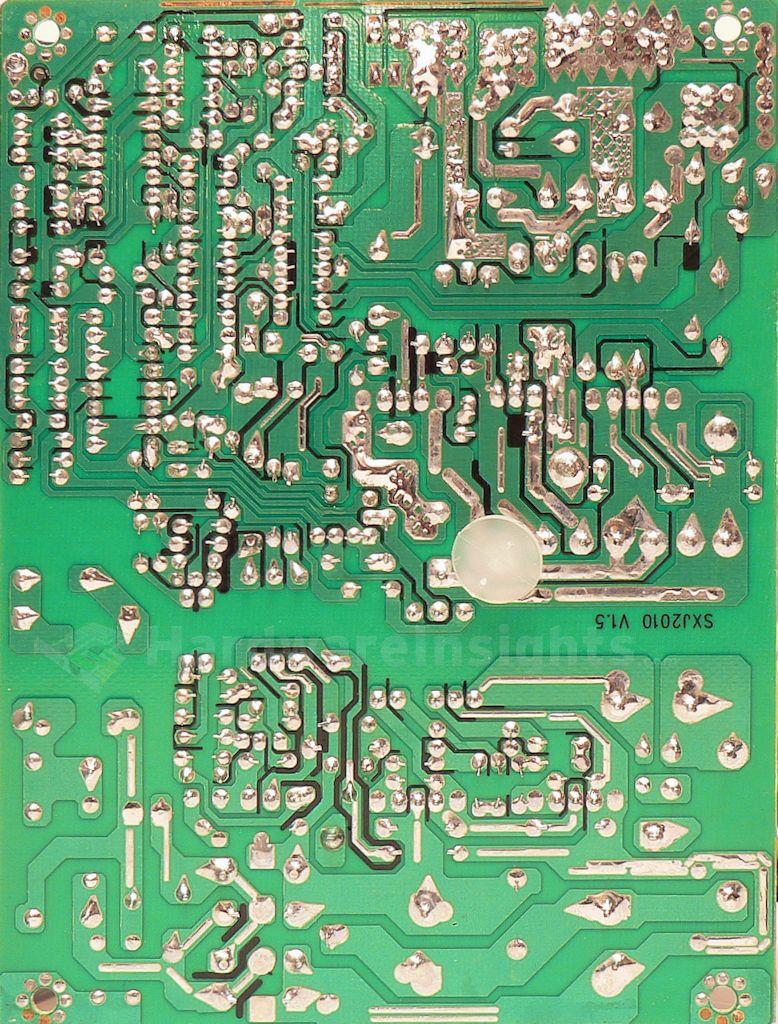
Notice this side of the board says SXJ2010 V1.5. Confusing the enemy here are we? Anyway, guess how the earth grounding wire (PE) is attached to this. It’s soldered to the board on secondary! It means it is connected with the chassis by two screws. Which may not be that bad after all…definitely better than just screwing it through one of the board screws to save half a cent. The soldering itself is not that bad actually, seems that the manufacturer made enough money to buy a bath and a few gas torches to make himself garage wave soldering line. Most of the electrodes are trimmed short enough but not all. There is actually even some path reinforcement here, I guess because of the “thickness” of the copper paths. If that’s even copper. I found 19 solder balls just on the component side and five more (3 of those very tiny though) on the solder side. I think this is my personal record. No need to count points for this I think…we already know how the ATX-350W is going to end.

