Contents
Load testing
Loading +5 V SB
As always, all load testing is done in accordance with our testing methodology. There has been just one small change. Now we’re using a different watt-meter, namely the Electrobock EMF-1. Besides it having a resolution of 0.1 W, I imagine that it is essentially the same as all the other inexpensive wall watt-meters. We see that the voltage regulation is not bad, it is tighter than 2%. In fact it is precisely only 1.2 %. Ripple suppression, along with the efficiency, is average.
| Output (W) | Load (A) | Voltage (V)/ ripple (mV) | Input (W) | Efficiency/power factor |
| 0 | 0 | 5.06/6.60 | 0 | —/0 |
| 12.00 | 2.40 | 5.00/11.0 | 15.7 | 76.4 %/0.53 |
| 16.61 | 3.34 | 4.98/8.40 | 21.4 | 77.6 %/0.55 |
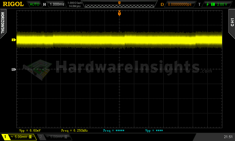
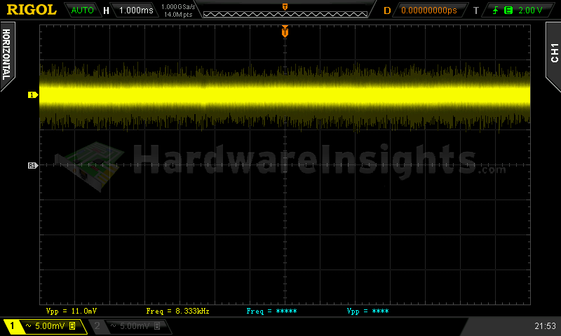
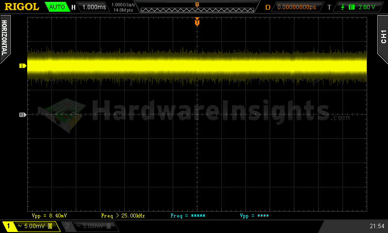
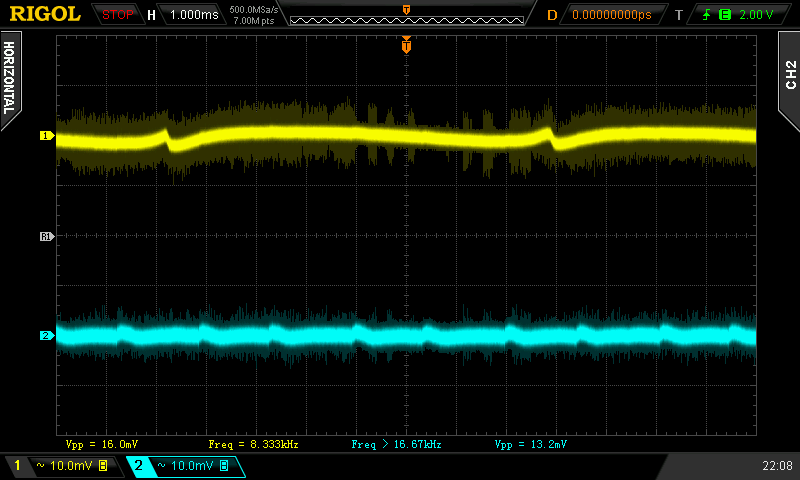
+5 V SB ripple (left to right): 0 A; 2.40 A; 3.34 A
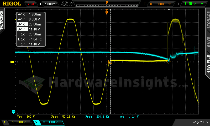
Voltage hold-up time
As we can see on the oscilloscope screenshot, the hold-up time of the +12 V rail is OK, being precisely 23.3 ms. This is an average value. What is nice about this is that the voltage dropped smoothly until we got to approximately 11.4 V (the ATX minimum), and only then did the unit shut itself off.
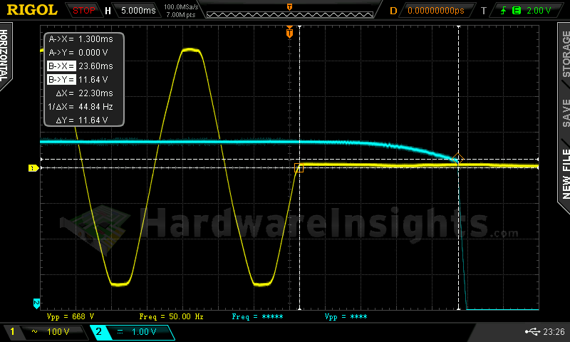
Trying to interrupt the power for exactly 23.3 ms revealed the maximum tolerated delay to be exactly a millisecond less, and the minimum voltage reached 11.4 V. After resuming the power there was some minor oscillation before stabilizing, but nothing too bad. Well, 22.3 ms should be more than enough for most UPS units to kick in.
Combined loading
Compared to the retail S12G unit I previously tested, the voltage regulation is pretty much as bad. Some rails were better, some rails were worse, and overall I would say that it’s practically the same. Seasonic just allows for too great a tolerance, and thus the final measurements produce results that manifest themselves over a wide spectrum. Compared to many competing units, these results are only barely average, and in the year 2016, I believe Seasonic units will be among the worst-performing high-end units with respect to this particular test. Another information I would like to repeat is the −12 V OCP. It is so tight it does not even let the Papst fan start at very slightly over 0.3 A nominal draw. The motor has higher start-up current, but it does not even start when already spinning. Seasonic should allow a few percent more than 0.3 A…this is way too strict.
| Output power | Load/ voltage +5 V SB | Load/ voltage +3.3 V | Load/ voltage +5 V | Load/ voltage +12 V | Load/ voltage −12 V | Input power | Efficiency/power factor |
| 5.0 %/ 27.53 W | 0 A/ 5.06 V | 0.027 A/ 3.36 V | 0.264 A/ 5.09 V | 1.946 A/ 12.17 V | 0.215 A/ −11.22 V | 38.3 W | 71.9 %/ 0.80 |
| 20 %/ 106.78 W | 0.491 A/ 5.04 V | 1.546 A/ 3.36 V | 2.206 A/ 5.08 V | 7.32 A/ 12.16 V | 0.215 A/ −11.34 V | 126.8 W | 84.2 %/ 0.97 |
| 40 %/ 227.45 W | 0.971 A/ 5.02 V | 2.95 A/ 3.37 V | 3.37 A/ 5.08 V | 16.21 A/ 12.14 V | 0.217 A/ −11.55 V | 257.8 W | 88.2 %/ 0.99 |
| 60 %/ 335.95 W | 1.44 A/ 5.00 V | 4.15 A/ 3.35 V | 4.89 A/ 5.08 V | 23.7 A/ 12.13 V | 0.217 A/ −11.73 V | 374.0 W | 89.8 %/ 1 |
|
80 %/ 441.01 W |
1.90 A/ 4.98 V | 5.62 A/ 3.36 V | 6.05 A/ 5.07 V | 31.3 A/ 12.12 V | 0.221 A/ −11.93 V | 494.4 W | 89.2 %/ 1 |
| 100 %/ 558.98 W | 2.35 A/ 4.96 V | 7.13 A/ 3.36 V | 6.75 A/ 5.07 V | 40.2 A/ 12.10 V | 0.223 A/ −12.21 V | 633.8 W | 88.2 %/ 1 |
As for the efficiency, the results this time around are much worse. Even ignoring the 1.5% difference of my new wattmeter as compared to the old wattmeter I used for the previous revision unit, there still seems to be at least another half a percent difference, which I believe can be attributed to them changing the semi-synchronous rectification to fully synchronous rectification, whereas the original design of this platform did not call for it. So, so far we have the same voltage regulation and slightly worse efficiency.
Combined loading ripple
The ripple suppression of the SSR-550RT prototype was still more or less OK during the second test, but starting with test three it all started going downhill. The ripple all-of-the-sudden virtually doubled, and that’s not all… no matter how I positioned the cables it could never perform in spec. It is also worth mentioning that I even made my own SATA connectors so that all them were terminated with 1 kΩ resistors. In the end, this unit completely failed the ripple suppression tests.
| Output % | Ripple +5 V SB | Ripple +3.3 V | Ripple +5 V | Ripple +12 V | Ripple −12 V |
| 5.0 | 24.4 mV | 16.4 mV | 26.8 mV | 14.4 mV | 16.0 mV |
| 20 | 25.6 mV | 18.4 mV | 24.4 mV | 20.4 mV | 16.0 mV |
| 40 | 49.6 mV | 35.2 mV | 47.2 mV | 40.0 mV | 28.8 mV |
| 60 | 62.4 mV | 44.0 mV | 52.8 mV | 36.8 mV | 37.6 mV |
| 80 | 71.2 mV | 45.6 mV | 59.2 mV | 56.8 mV | 46.4 mV |
| 100 | 60.0 mV | 30.4 mV | 55.2 mV | 53.6 mV | 50.4 mV |
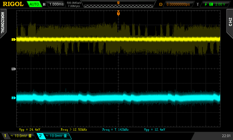
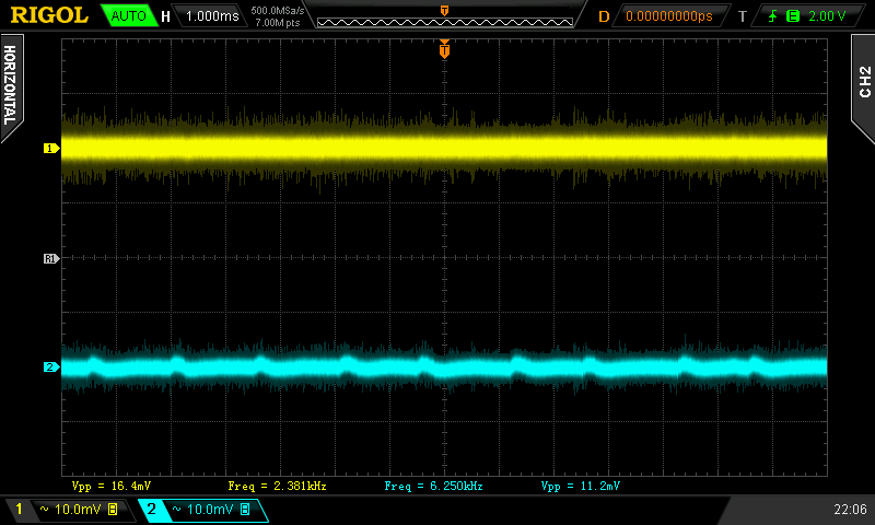
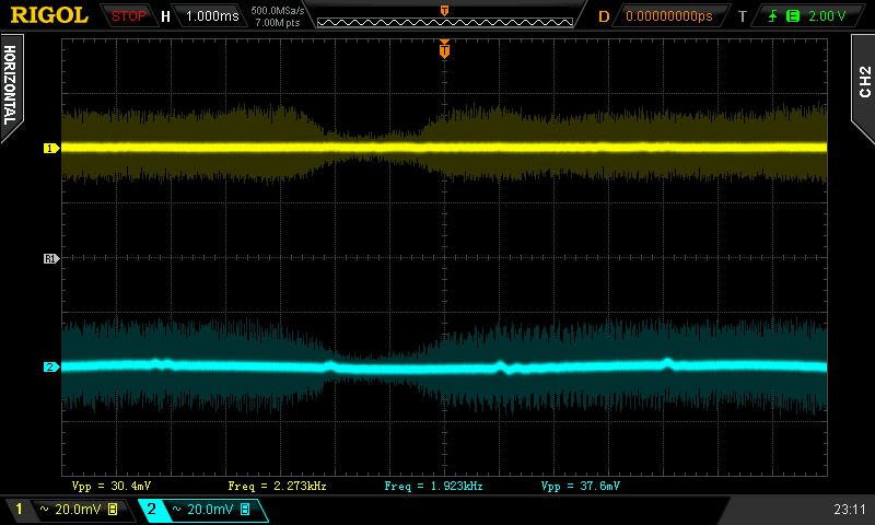
Ripple 5% load (left to right): +5 V SB; +3.3 V; +5 V; −12 V . The second channel is connected to +12 V.
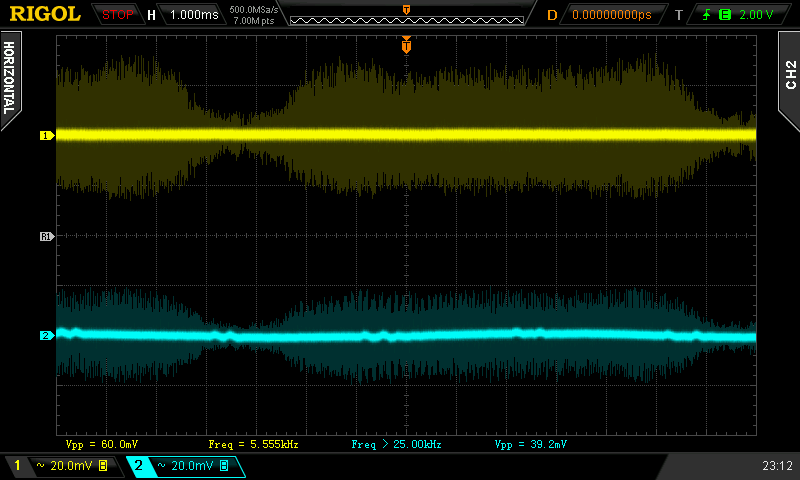
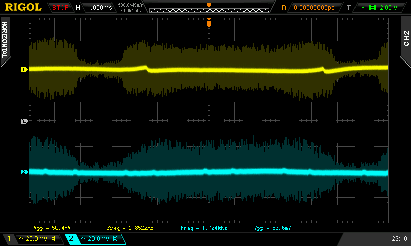
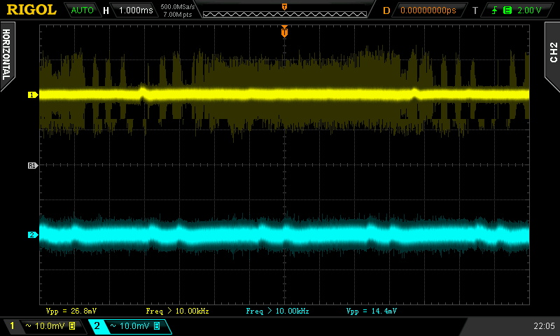
Ripple 100% load (left to right): +5 V SB; +3.3 V; +5 V; −12 V. The second channel is connected to +12 V.
Crossloading, overloading
Not much change here. The voltage regulation is the same, and efficiency is also similarly lower. The only change here is that this time around the unit survived the combined overloading test, albeit with quite low efficiency.
| Output power | Load/ voltage +5 V SB | Load/ voltage +3.3 V | Load/ voltage +5 V | Load/ voltage +12 V | Load/ voltage −12 V | Input power | Efficiency/power factor |
| 18 %/ 97.53 W | 0.469 A/ 5.03 V | 20.06 A/ 3.36 V | 0.280 A/ 5.08 V | 1.961 A/ 12.17 V | 0.218 A/ −11.36 V | 120.7 W | 80.8 %/ 0.96 |
| 24 %/ 130.15 | 0.482 A/ 5.03 V | 0.027 A/ 3.35 V | 20.00 A/ 5.07 V | 1.956 A/ 12.17 V | 0.214 A/ −11.40 V | 153.6 W | 84.7 %/ 0.98 |
| 100 %/ 548.02 W | 0.492 A/ 5.02 V | 0.088 A/ 3.35 V | 0.299 A/ 5.07 V | 44.7 A/ 12.10 V | 0.235 A/ −12.22 V | 621.1 W | 88.2 %/ 1 |
| 129 %/ 710.74 W | 3.22 A/ 4.92 V | 10.95 A/ 3.35 V | 12.25 A/ 5.06 V | 49.2 A/ 12.06 V | 0.229 A/ −12.67 V | 829.7 W | 85.7 %/ 1 |
This prototype unit also exhibited some strange behavior where it would sometimes unexpectedly shut down, and the only way to get it to turn back on was to cycle the AC switch, but at least it didn’t burn. It worked fine after 15 minutes in the sweater and shut down within two minutes after blocking the fan from spinning. So all the protections do indeed seem to be functioning properly now!
Crossloading, overloading ripple
The ripple was slightly lower this time but still went out of spec on two tests.
| Output % | Ripple +5 V SB | Ripple +3.3 V | Ripple +5 V | Ripple +12 V | Ripple −12 V |
| 18 | 26.4 mV | 15.2 mV | 25.6 mV | 11.2 mV | 14.0 mV |
| 24 | 28.4 mV | 16.0 mV | 28.4 mV | 12.4 mV | 20.8 mV |
| 100 | 52.0 mV | 31.2 mV | 44.0 mV | 32.0 mV | 40.8 mV |
| 129 | — | — | 56.0 mV | 26.8 mV | — |
Fan speed and temperatures
The unit’s fan started spinning at slightly over 500 RPM, this speed was maintained until test four when the speed doubled. Under 80% load it was already running at 1900 RPM. The fan does spin slightly slower than before, and having fluid bearing, it wasn’t as loud, so I could hear it over the sound of my load tester. But at 1900RPM it was anything but silent.
| Output % | Fan speed (RPM) | Temperature intake/ outtake |
| 5.0 | 523 | 23 °C/ 25 °C |
| 20 | 533 | 24 °C/ 26 °C |
| 40 | 553 | 24 °C/ 26 °C |
| 60 | 1007 | 24 °C/ 29 °C |
| 80 | 1898 | 25 °C/ 29 °C |
| 100 | 1937 | 25 °C/ 28 °C |
| CL 18 | 554 | 24 °C/ 29 °C |
| CL 24 | 581 | 24 °C/ 28 °C |
| CL 100 | 1919 | 25 °C/ 31 °C |
| OL 129 | 1918 | 25 °C/ 30 °C |
Temperatures were rather low overall, but that has to do with the high fan speed, and the increased airflow.

