Contents
- 1Introducing the Be Quiet! Straight Power 10 700 W CM (E10-CM-700W)
- 1.1Packaging and accessories
- 2Connectors & cabling
- 2.1Casing & cooling
- 3Input filtering
- 4Primary side
- 4.1+5 V stand-by rail
- 5Secondary side
- 5.1Build quality
- 6Load testing
- 6.1Loading +5 V SB
- 6.2Hold-up time
- 6.3Combined loading
- 6.4Combined loading ripple
- 6.5Crossloading, overloading
- 6.6Crossloading, overloading ripple
- 6.7Fan speed, temperatures and noise
- 7Conclusion and evaluation
- 7.1Thanks
- 7.2Discussion
Input filtering
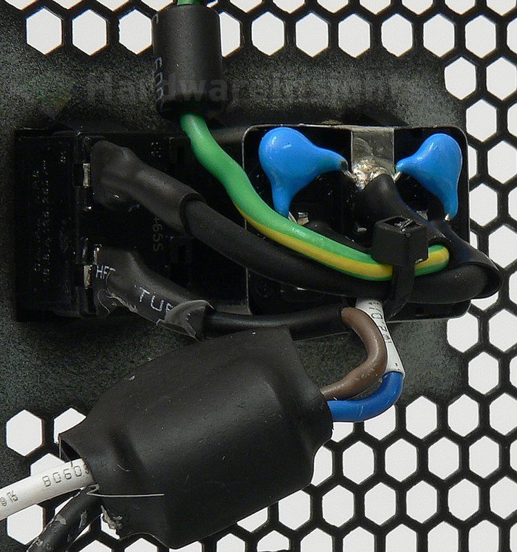
The input filtering begins with its first stage directly on the input receptacle. There are two ceramic Y capacitors on it. The receptacle is partially shielded. The wires leading to the main board as well as the grounding wire also have ferrite rings on them.
If we move to the main board, we can see that there are two more Y capacitors (plus a fifth one between the primary common and earth ground). There are also two X capacitors, two common mode chokes and a varistor (on the right side, with heatshrink sleeving).
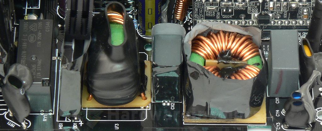
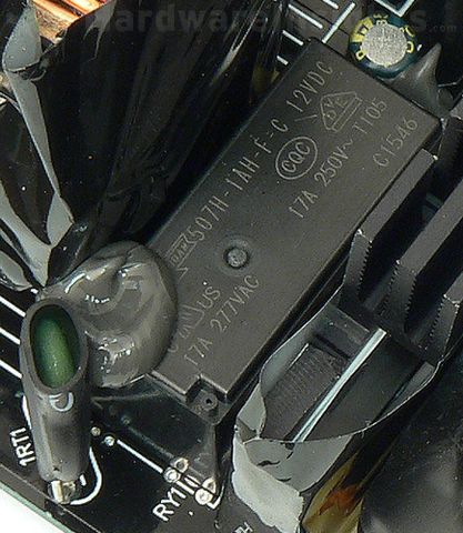
There’s also a sleeved thermistor with a relay bypass to lower losses. A lone Teapo SC 47/35 filters the power for the coil.
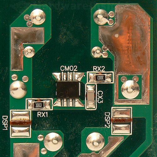
Be Quiet! actually implemented an X capacitor discharge circuit via a microchip. It’s the Champion Micro CM03X which also prevents losses when the unit is connected to the wall.
The X capacitors (between the live and neutral) and Y capacitors (between live and ground/neutral and ground) are used to filter out high-frequency ripple that emanates from the power grid. That is the noise of which manifests in the form of feedback from electronic devices which lack adequate filtering due to cost cutting. But also from devices where filtering was very difficult to implement (powerful devices, e.g. microwave ovens). It also prevents ripple from this unit itself from feeding back into the grid.
Chokes are used for the same reason, and together with the X/Y capacitors they form an input filter. Such filters are often made as one component, they may also be integrated together with AC receptacle. These components may also (partially) help to filter smaller voltage spikes in the power grid. To suppress more serious spikes (for example from distant lightning strikes hitting the power grid), the MOV (metal-oxide varistor) is used. Thermistor is then used to suppress current spikes when first connecting the unit to power (i.e. flipping the power switch).
The Y capacitors are also often situated between the high-voltage primary and the low-voltage secondary sides. These days, more Y capacitors are used even between primary common (ground after an input rectifier) and earth ground to suppress internal interference and keep it from getting to the secondary side. It is because really high-frequency ripple goes everywhere it can to some extent (including coupling through the insulation, metal casing etc…). That is also why the AC wires themselves are often inserted through the ferrite toroid inductor (to suppress such coupling).

