Contents
- 1Introducing the Xilence XP400R6
- 1.1Packaging and accessories
- 2Connectors & cabling
- 2.1Casing & cooling
- 3Input filtering
- 4Primary side
- 4.1+5 V stand-by rail
- 5Secondary side
- 5.1Build quality
- 6Load testing
- 6.1Loading +5 V SB
- 6.2Voltage hold-up time
- 6.3Combined loading
- 6.4Combined loading ripple
- 6.5Crossloading, overloading
- 6.6Crossloading, overloading ripple
- 6.7Fan speed and temperatures
- 7Conclusion and evaluation
- 7.1Discussion
Input filtering
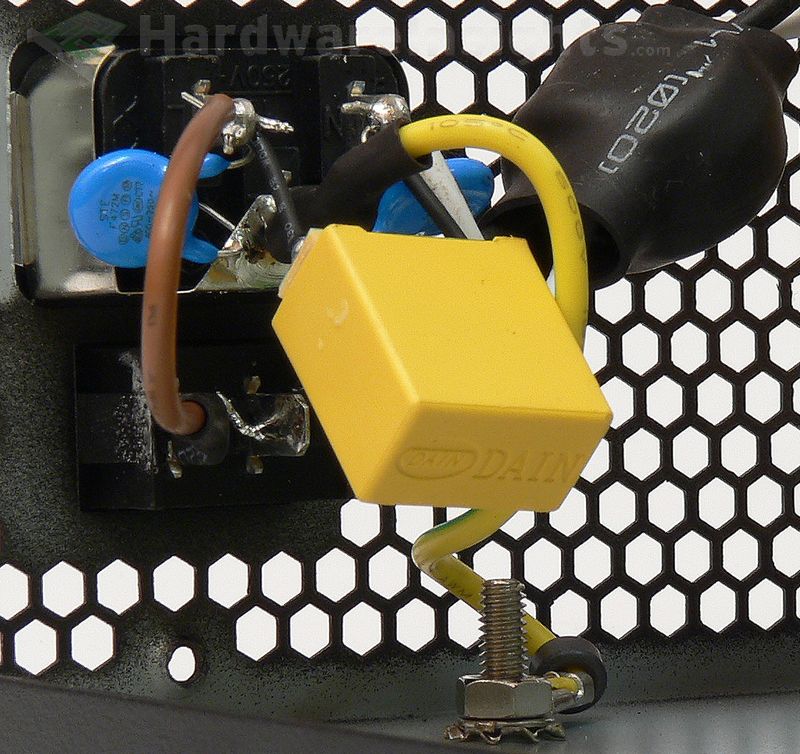
As usual, the input filtering starts with components soldered directly onto the input receptacle. There are two ceramic Y capacitors and one film X capacitor, plus a small ferrite ring on the earth wire (and a larger ferrite core on the AC wires). You may notice there is something soldered on the X-cap – that’s a small PCB carrying a diode-sized “IC” which seems to be some sort of intelligent discharge circuit, which is coupled together with an SMD ceramic capacitor and two resistors by which means causes the primary capacitor to be discharged upon powering the unit off. It is very unusual to find something like this in such an inexpensive unit.
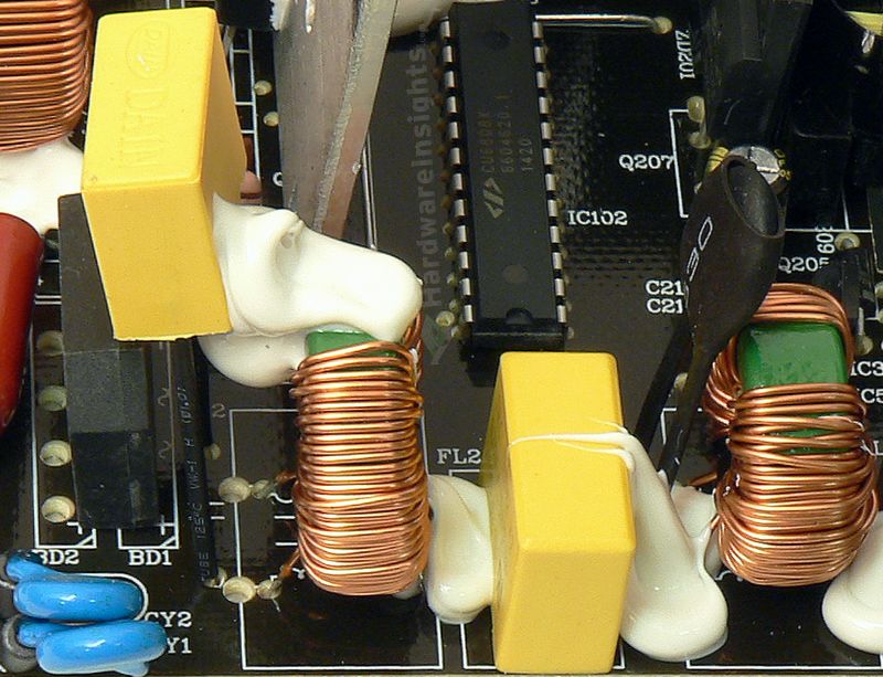
There’s even a group of unpopulated areas for another set of exactly such components on the solder side of the main board, where the second filtering stage is located. We have two more X capacitors, two more Y capacitors (with small ferrite beads on their legs) and two common-mode chokes (which have really thin wires). There’s also a thermistor with actual heatshrink, but no varistor is present. Indeed, I should be able to add some components myself, as there are vacant spots for bigger coils (for higher-power versions of the unit). Overall this is pretty good so far, and besides for the absent varistor, we have a full input filter inside the XP400R6! Maybe times are perhaps changing for the better after all?
The X capacitors (between the live and neutral) and Y capacitors (between live and ground/neutral and ground) are used to filter out high-frequency ripple that emanates from the power grid. That is the noise of which manifests in the form of feedback from electronic devices which lack adequate filtering due to cost cutting, but also from devices where filtering was very difficult to implement (powerful devices, i.e. microwave ovens). It also prevents ripple from this unit itself from feeding back into the grid.
Chokes are used for the same reason, and together with the X/Y capacitors they form an input filter. Such filters are often made as one component, they may also be integrated together with AC receptacle. These components may also (partially) help to filter smaller voltage spikes on the power grid. To suppress more serious spikes (for example from distant lightning strikes hitting the power grid), the MOV (metal-oxide varistor) is used. Thermistor limits current inrush when first connecting the unit to power (i. e. flipping the power switch).
The Y capacitors are also often situated between the high-voltage primary and the low-voltage secondary sides. These days, more Y capacitors are used even between primary common (ground after an input rectifier) and earth ground to suppress internal interference and keep it from getting to the secondary side. This is because really high-frequency ripple goes everywhere it can to some extent (including coupling through the insulation, metal casing etc…). That is also why the AC wires themselves are often inserted through the ferrite toroid inductor (to suppress such coupling).

