Contents
- 1Introduction
- 1.1Packaging and accessories
- 2Connectors & cabling
- 2.1Casing & cooling
- 3Input filtering
- 4Primary side
- 4.1+5 V stand-by rail
- 5Secondary side
- 5.1Build quality
- 6Load testing
- 6.1Loading +5 V SB
- 6.2Voltage hold-up time
- 6.3Combined loading
- 6.4Combined loading ripple
- 6.5Crossloading, overloading
- 6.6Crossloading, overloading ripple
- 6.7Fan speed and temperatures
- 7Conclusion and evaluation
- 7.1Thanks
- 8Addendum - working on the unit
- 8.1Discussion
Load testing
Loading +5 V SB
As always, all load testing is done according to our testing methodology. There has been just one small change. Now we’re using a different watt-meter, namely the Electrobock EMF-1. Besides it having a resolution of 0.1 W, I imagine that it is essentially the same as all the other inexpensive wall watt-meters. We see that the voltage regulation corresponds with mainstream units, it is within ±3 %.
| Output (W) | Load (A) | Voltage (V)/ ripple (mV) | Input (W) | Efficiency/power factor |
| 0 | 0 | 5.14/13.6 | 0 | —/0 |
| 12.16 | 2.44 | 4.99/16.4 | 16.4 | 74.1 %/0.45 |
| 16.73 | 3.39 | 4.93/16.4 | 22.8 | 73.4 %/0.50 |
Ripple suppression is just as bad here and the efficiency is under 75 %. Mainstream unit indeed.
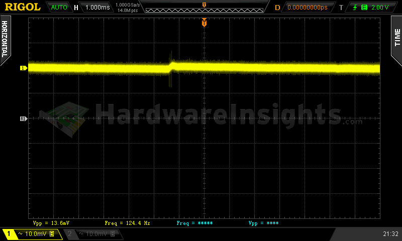
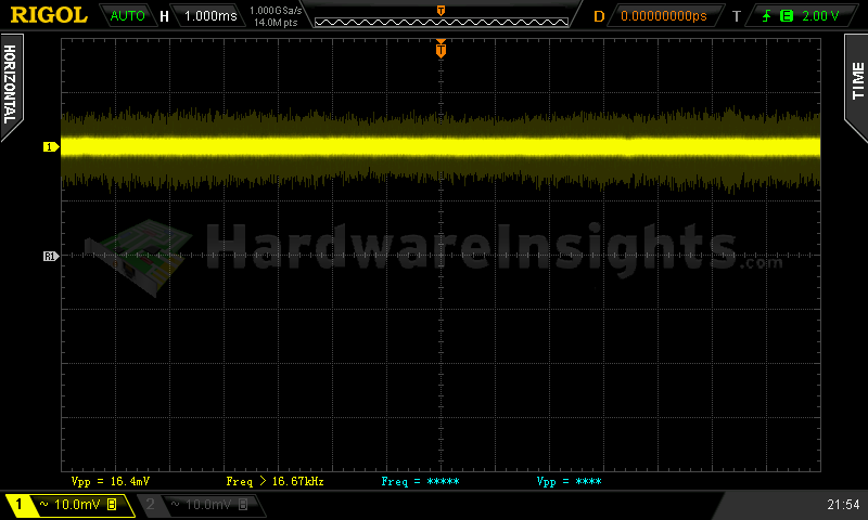
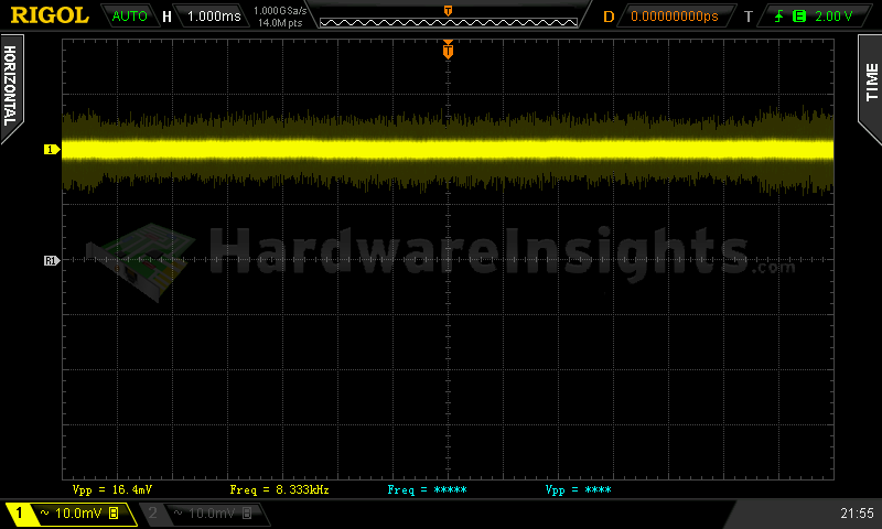
+5 V SB ripple (left to right): 0 A; 2.44 A; 3.39 A
Voltage hold-up time
As we can see on the oscilloscope screenshot, the hold-up time of the +12 V rail is OK, preciselly 19.1 ms. I would expect somewhat more though as the input capacitor has quite a high capacity for a 500W unit. It seems that the switching section is not that effective in using their stored energy, but then again, let’s consider here that this is only Bronze rated.
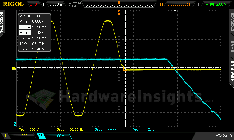
Trying to interrupt the power for 19.1 ms revealed that the hold-up time is within spec, however, a transient spike with quite a high voltage did appear. It went as high as a little over 13.5 V.
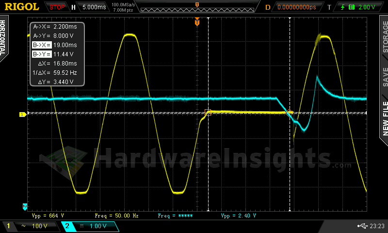
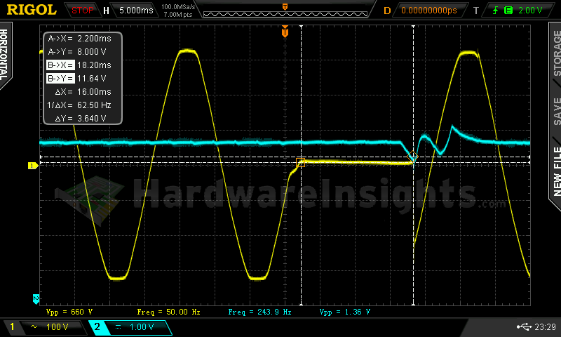
Further decreasing the hold-up time was neccessary for the unit to fully comply with the ATX in terms of voltage regulation. In order to reach this spec I had to decrease it all the way down to 16ms, which is quite low if you ask me.
Combined loading
Combined loading was OK for the Zalman ZM500-GVM. Firstly, let’s talk about the voltage regulation. As this is a group design, it’s pretty obvious that the regulation will be only so-so when all the rails are properly loaded. I managed to more or less do that while not drawing insane amounts of power from the +3.3 or +5 V rails, which aren’t reall too stressed in modern-day computers. We can see that the +5 V rail still dropped from the preferred ±3% margin, and in test one it reached as much as 5.17 V. Well, things could still be worse I guess. The -12 V rail was fairly OK though.
| Output power | Load/ voltage +5 V SB | Load/ voltage +3.3 V | Load/ voltage +5 V | Load/ voltage +12 V | Load/ voltage −12 V | Input power | Efficiency/power factor |
| 5.5 %/ 27.38 W | 0 A/ 5.13 V | 0 A/ 3.37 V | 0.313 A/ 5.17 V | 1.849 A/ 12.04 V | 0.304/ −11.51 V | 37.8 W | 72.4 %/ 0.54 |
| 20 %/ 102.76 W | 0.544 A/ 5.10 V | 1.497 A/ 3.36 V | 1.528 A/ 5.14 V | 7.19 A/ 12.05 V | 0.314/ −11.66 V | 125.1 W | 82.2 %/ 0.93 |
| 40 %/ 194.83 W | 1.04 A/ 5.06 V | 2.89 A/ 3.34 V | 3.44 A/ 5.12 V | 13.21 A/ 12.05 V | 0.300 A/ −11.77 V | 230.1 W | 84.7 %/ 0.97 |
| 60 %/ 301.48 W | 1.55 A/ 5.02 V | 5.12 A/ 3.33 V | 4.92 A/ 5.10 V | 20.63 A/ 12.02 V | 0.304 A/ −11.85 V | 349.3 W | 86.3 %/ 0.98 |
|
80 %/ 400.44 W |
1.90 A/ 4.99 V | 5.94 A/ 3.31 V | 6.08 A/ 5.10 V | 28.1 A/ 11.98 V | 0.306 A/ −11.93 V | 468.2 W | 85.5 %/ 0.98 |
| 100 %/ 500.73 W | 2.35 A/ 4.95 V | 7.25 A/ 3.31 V | 7.92 A/ 5.08 V | 35.2 A/ 11.96 V | 0.305 A/ −12.03 V | 596.8 W | 83.9 %/ 0.98 |
As for the overall efficiency, we reached over 86 %. I found it written somewhere in the manual though that peak efficiency should reach 88 %. Taking into account the margin of error on my current watt meter, I think this number is pretty accurate. The low-load efficiency is quite bad though.
Combined loading ripple
Initially, the ripple suppression of the Zalman ZM500-GVM looked nice, but when it came to test four, the values on the +5 V SB rose very high, until they went through the roof. Then the +3.3 and +5 V rails also dropped out of their specified maximum value. It seems that the 2000 μF overall filtering capacity (4400 for the +3.3 V rail) is just too low for this platform with 500 W. The result here is as bad as the Silverstone Essential Series we reviewed last time.
| Output % | Ripple +5 V SB | Ripple +3.3 V | Ripple +5 V | Ripple +12 V | Ripple −12 V |
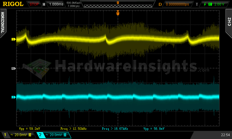
| 5.5 | 27.6 mV | 16.0 mV | 16.0 mV | 31.2 mV | 20.8 mV |
| 20 | 36.8 mV | 19.2 mV | 19.2 mV | 46.4 mV | 22.4 mV |
| 40 | 39.2 mV | 22.0 mV | 22.0 mV | 38.4 mV | 24.0 mV |
| 60 | 48.8 mV | 27.2 mV | 27.2 mV | 50.4 mV | 29.6 mV |
| 80 | 84.0 mV | 43.2 mV | 43.2 mV | 54.4 mV | 61.6 mV |
| 100 | 100.0 mV | 62.4 mV | 58.4 mV | 71.2 mV | 59.2 mV |
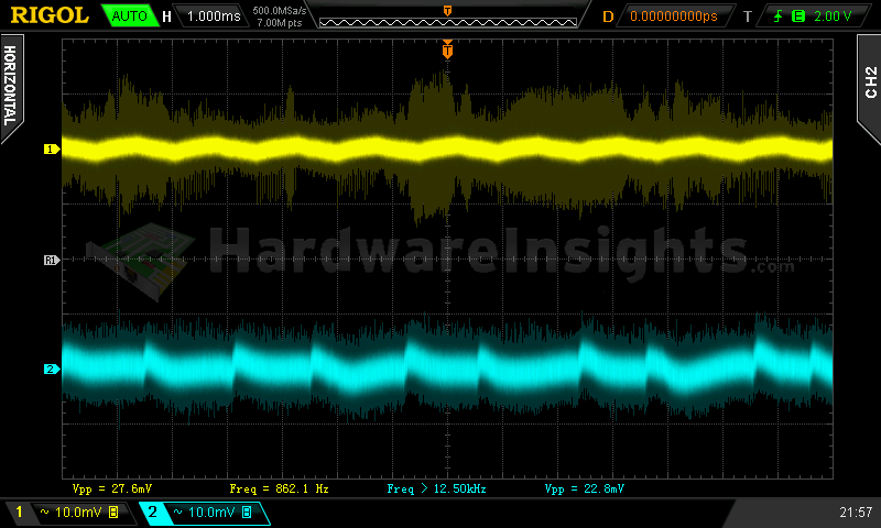
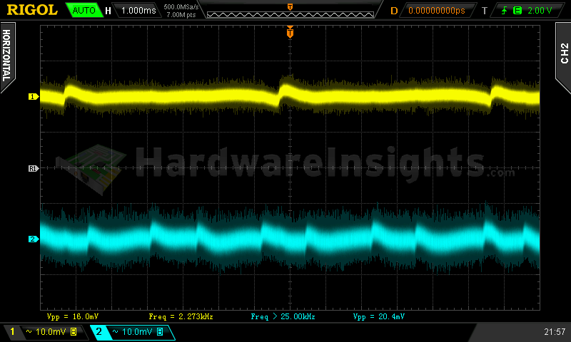
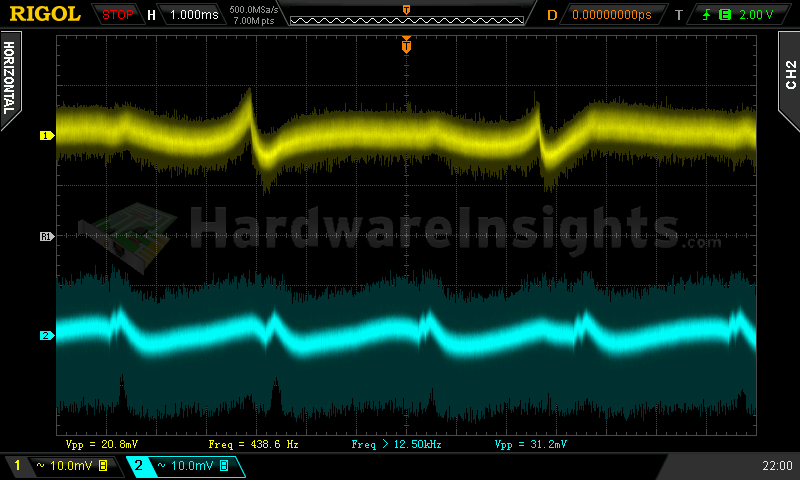
Ripple 5.5% load (left to right): +5 V SB; +3.3 V; +5 V; −12 V . The second channel is connected to +12 V.
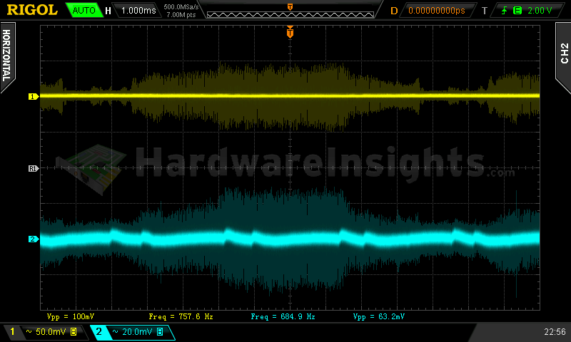
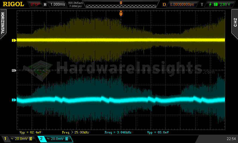
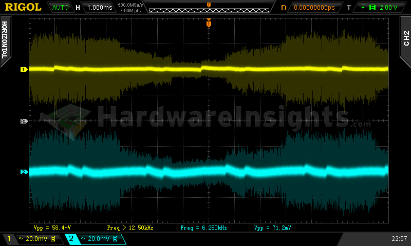
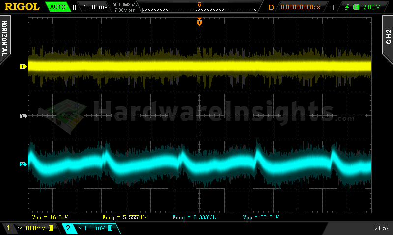
Ripple 100% load (left to right): +5 V SB; +3.3 V; +5 V; −12 V. The second channel is connected to +12 V.
Crossloading, overloading
Crossloading tests really stressed the group-design aspect here, as was expected. The only positive results I got was with quite a low load on all the rails — only then did the unit manage to stay within specification, albeit only barely, considering that the +12 V rail reached 12.60 V, and the +5 V fell all the way to 4.77 V. But that is still within spec. Crossload efficiency was quite low. I did try the maximum load on all the positive rails, but as we have already established, there is no OCP, so no safeguards kicked in.
| Output power | Load/ voltage +5 V SB | Load/ voltage +3.3 V | Load/ voltage +5 V | Load/ voltage +12 V | Load/ voltage −12 V | Input power | Efficiency/power factor |
| 21 %/ 103.39 W | 0.545 A/ 5.08 V | 20.50 A/ 3.26 V | 1.506 A/ 5.07 V | 1.877 A/ 12.16 V | 0.286 A/ −11.65 V | 142.1 W | 72.8 %/ 0.93 |
| 26 %/ 128.83 W | 0.544 A/ 5.08 V | 1.48 A/ 3.34 V | 19.50 A/ 4.77 V | 1.941 A/ 12.60 V | 0.304 A/ −12.05 V | 164.9 W | 78.1 %/ 0.95 |
| 90 %/ 452.11 W | 0.539 A/ 5.07 V | 1.46 A/ 3.33 V | 1.533 A/ 5.23 V | 36.9 A/ 11.73 V | 0.311 A/ −11.84 V | 532.7 W | 84.9 %/ 0.98 |
| 146 %/ 730.30 W | 3.28 A/ 4.83 V | 6.68 A/ 3.26 V | 16.16 A/ 4.94 V | 50.8 A/ 11.99 V | 0.312 A/ −12.31 V | 894.5 W | 81.6 %/ 0.99 |
On the other hand, I must admit that I am very surprised that the unit does indeed have working over power protection. It kicked in at around the advertised maximum limit, which in this case was 730 W. That is an almost 150 % overload! And all voltages were still within specified values! As for the Sweater test, the unit managed to work for 15 minutes, and by then it was already smelling pretty bad. Upon opening the sweater, I was able to measure the fan speed at around 1682 RPM, and the exhaust temperature at over 65 °C. It must have been much hotter than that inside, and I bet that if I had left the sweater on any longer, the unit would have caught fire.
Crossloading, overloading ripple
Well, the ripple was definitely not within spec, especially during the combined overloading tests. This may very well be the highest ripple value I have ever seen in my entire life!
| Output % | Ripple +5 V SB | Ripple +3.3 V | Ripple +5 V | Ripple +12 V | Ripple −12 V |
| 21 | 52.8 mV | 19.2 mV | 32.8 mV | 34.4 mV | 26.4 mV |
| 26 | 51.2 mV | 20.8 mV | 34.4 mV | 36.8 mV | 27.2 mV |
| 90 | 90.0 mV | 54.4 mV | 48.8 mV | 57.6 mV | 41.6 mV |
| 122 | 182 mV | — | — | 73.6 mV | — |
Fan speed and temperatures
This unit’s fan started spinning right after turning the PSU on. During the first three tests, the speed was roughly 650 RPM, then it started increasing approximately by 300 RPM after each test.
| Output % | Fan speed (RPM) | Temperature intake/ outtake |
| 5.5 | 657 | 23 °C/ 25 °C |
| 20 | 663 | 24 °C/ 27 °C |
| 40 | 682 | 24 °C/ 32 °C |
| 60 | 1089 | 24 °C/ 36 °C |
| 80 | 1382 | 25 °C/ 40 °C |
| 100 | 1692 | 26 °C/ 42 °C |
| CL 21 | 1274 | 24 °C/ 34 °C |
| CL 26 | 1082 | 24 °C/ 34 °C |
| CL 90 | 1423 | 26 °C/ 41 °C |
| OL 149 | 1755 | 27 °C/ 45+ °C |
The highest air temperature measured at the exhaust was at over 45 °C, and that was measured at no load, turning on the unit after the combined-load overheating tests. I would be afraid to use this in much more than 30 °C ambient temperature and with bad case cooling, and even under these conditions it would already mean pushing the unit. At least it does have quality capacitors though which should survive very long even at these higher temperatures.

