Contents
- 1Introducing the Zalman ZM600-GVM
- 1.1Packaging and accessories
- 2Connectors & cabling
- 2.1Casing & cooling
- 3Input filtering
- 4Primary side
- 4.1+5 V stand-by rail
- 5Secondary side
- 5.1Build quality
- 6Load testing
- 6.1Loading +5 V SB
- 6.2Voltage hold-up time
- 6.3Combined loading
- 6.4Combined loading ripple
- 6.5Crossloading, overloading
- 6.6Crossloading, overloading ripple
- 6.7Fan speed and temperatures
- 7Conclusion and evaluation
- 7.1Thanks
- 7.2Discussion
Load testing
Loading +5 V SB
As always, all load testing is done according to our testing methodology. There has been just one small change. Now we’re using a different watt-meter, namely the Electrobock EMF-1. Besides it having a resolution of 0.1 W, I imagine that it is essentially the same as all the other inexpensive wall watt-meters. We see that the voltage regulation corresponds with mainstream units, it is within ±3 %.
| Output (W) | Load (A) | Voltage (V)/ ripple (mV) | Input (W) | Efficiency/power factor |
| 0 | 0 | 5.14/14.0 | 0 | —/0 |
| 12.21 | 2.45 | 4.99/16.4 | 16.6 | 73.6 %/0.48 |
| 16.75 | 3.40 | 4.93/18.0 | 23.0 | 72.8 %/0.50 |
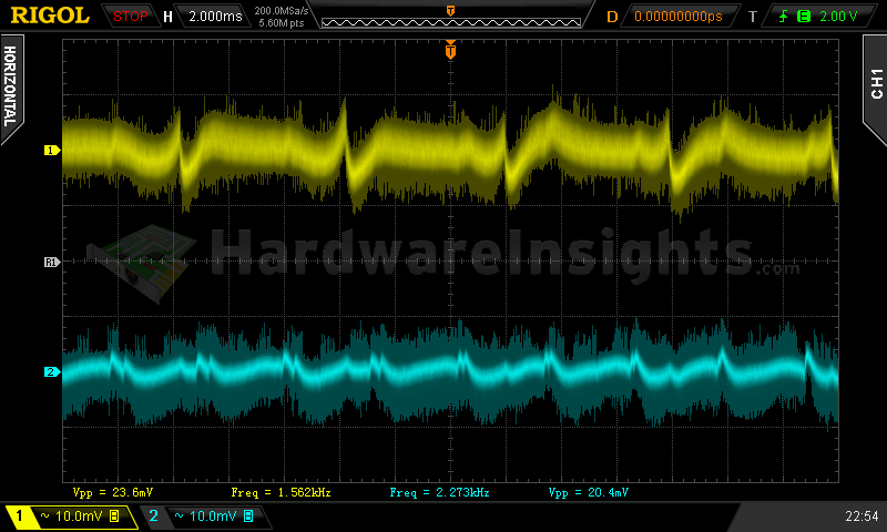
Ripple suppression is just as bad here and the efficiency is under 75 %. Basically the same results as with the ZM500-GVM. After all, the stand-by supply is the same in the ZM600-GVM.
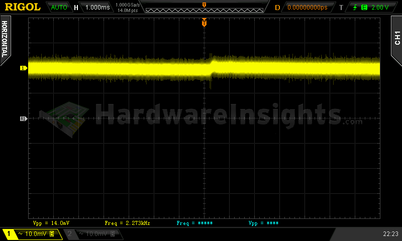
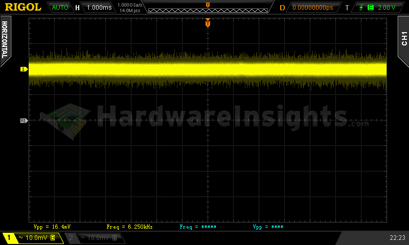
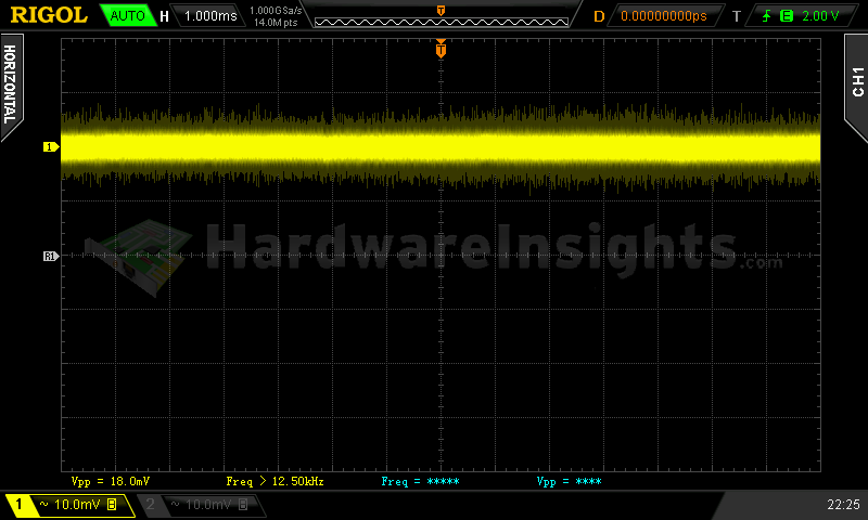
+5 V SB ripple (left to right): 0 A; 2.45 A; 3.40 A
Voltage hold-up time
As we can see on the oscilloscope screenshot, the hold-up time of the +12 V rail is even lower than with the 500W version, precisely 14.2 ms. It is surely also because the input capacitor remained at 330 μF, which is not that much for 600W Bronze unit. Also it seems that the switching section is not that effective in using its stored energy, but then again, let’s consider here that this has lower efficiency.
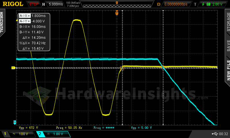
Trying to interrupt the power for 14.2 ms revealed that this time is really accurate, the voltage was within spec right away. This value is less than ATX minimum so being very strict, I would already not let it pass. but I somewhat counted with such cases when I have been adding the hold-up time measurements into my methodology and decided be somewhat tolerant in this test. For that reason I selected 10 ms as absolute minimum, as under that value most units will fail even with UPS in front of them, as the switching times of UPSes are usually specified around this value.
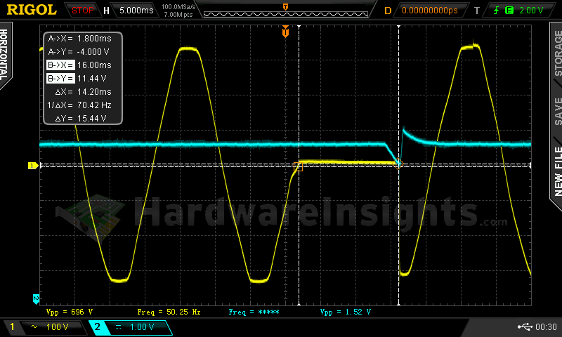
I even checked the Power Good output this time just to be sure, it is about the same, 14.3 ms.
Combined loading
Combined loading was OK for the Zalman ZM600-GVM. Firstly, let’s talk about the voltage regulation. As this is a group design, it’s pretty obvious that the regulation will be only so-so when all the rails are properly loaded. This time I focused slightly more on the +12 V rail, which resulted in lower voltage there. We can see that the +5 V rail still dropped from the preferred ±3% margin, and in test one it reached as much as 5.17 V. Well, things could still be worse I guess. The −12 V rail was fairly OK though.
| Output power | Load/ voltage +5 V SB | Load/ voltage +3.3 V | Load/ voltage +5 V | Load/ voltage +12 V | Load/ voltage −12 V | Input power | Efficiency/power factor |
| 4.5 %/ 27.19 W | 0 A/ 5.13 V | 0 A/ 3.38 V | 0.321 A/ 5.17 V | 1.832 A/ 12.06 V | 0.299 A/ −11.51 V | 38.3 W | 71.0 %/ 0.45 |
| 20 %/ 127.40 W | 0.547 A/ 5.09 V | 1.506 A/ 3.38 V | 1.525 A/ 5.15 V | 9.25 A/ 12.04 V | 0.303 A/ −11.68 V | 153.1 W | 83.2 %/ 0.92 |
| 40 %/ 243.05 W | 1.04 A/ 5.06 V | 2.89 A/ 3.37 V | 4.91 A/ 5.10 V | 16.83 A/ 12.07 V | 0.304 A/ −11.83 V | 284.6 W | 85.4 %/ 0.96 |
| 60 %/ 366.66 W | 1.56 A/ 5.02 V | 4.50 A/ 3.36 V | 6.07 A/ 5.09 V | 25.7 A/ 12.03 V | 0.307 A/ −11.92 V | 426.2 W | 86.0 %/ 0.97 |
|
80 %/ 479.29 W |
1.90 A/ 4.99 V | 5.89 A/ 3.35 V | 7.91 A/ 5.07 V | 33.8 A/ 12.02 V | 0.308 A/ −12.02 V | 562.5 W | 85.2 %/ 0.98 |
| 100 %/ 596.64 W | 2.37 A/ 4.95 V | 7.22 A/ 3.35 V | 9.20 A/ 5.06 V | 42.6 A/ 11.98 V | 0.314 A/ −12.11 V | 712.9 W | 83.7 %/ 0.98 |
As for the overall efficiency, we reached over 86 %. I found it written somewhere in the manual though that peak efficiency should reach 88 %. Taking into account the margin of error on my current watt meter, I think this number is pretty accurate. The low-load efficiency is quite bad though.
Combined loading ripple
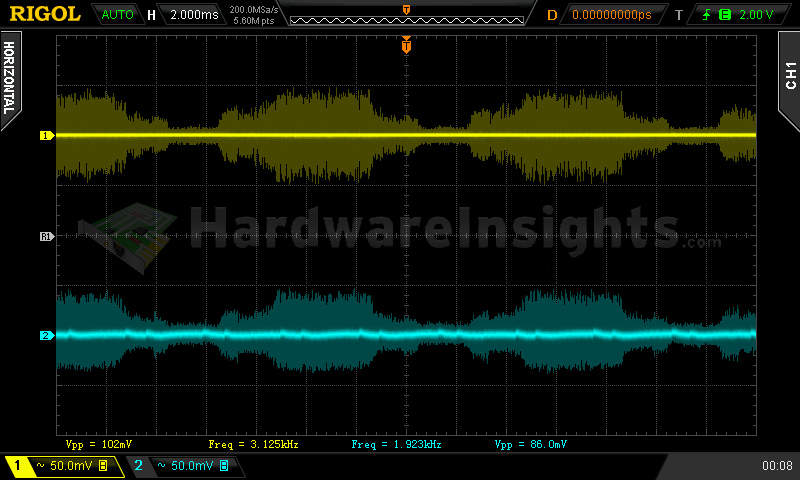
Initially, the ripple suppression of the Zalman ZM600-GVM looked even better than that of the 500W model, but when it came to test four, most of the values doubled, until they went through the roof completely. This result is similarly bad as with the ZM-500GVM. Once again there are chunks of time when high-frequency ripple of high amplitude appears.
| Output % | Ripple +5 V SB | Ripple +3.3 V | Ripple +5 V | Ripple +12 V | Ripple −12 V |
| 4.5 | 11.2 mV | 12.8 mV | 9.60 mV | 22.4 mV | 23.6 mV |
| 20 | 16.4 mV | 21.6 mV | 11.6 mV | 33.6 mV | 27.6 mV |
| 40 | 29.6 mV | 25.6 mV | 33.2 mV | 37.6 mV | 29.2 mV |
| 60 | 74.4 mV | 90.0 mV | 63.2 mV | 98.0 mV | 34.8 mV |
| 80 | 112.0 mV | 110.0 mV | 72.0 mV | 90.0 mV | 71.2 mV |
| 100 | 102.0 mV | 104.0 mV | 78.0 mV | 128.0 mV | 60.0 mV |
I went ahead and started with the modifications after finishing the review. This time I wanted to experiment step by step to discover which component plays crucial role. And it was not really necessary. Just by populating the CY4 spot with 222M Y2 capacitor, the ripple in test four dropped about 80 mV so then it was well within spec at approx. 35 mV. The right cap in the wrong place can make all the difference in the world…a 1 US cent cap…
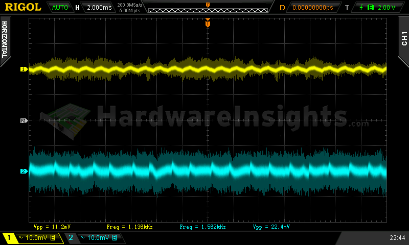
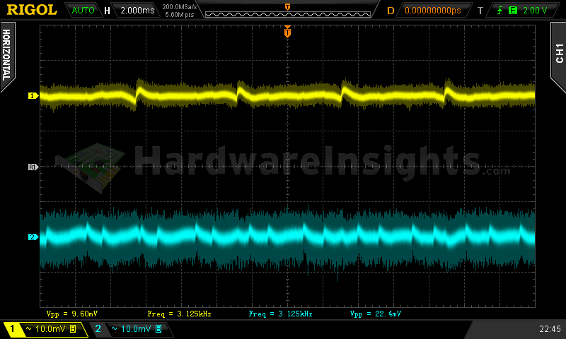
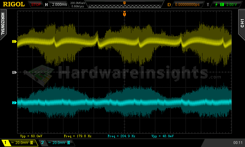
Ripple 4.5% load (left to right): +5 V SB; +3.3 V; +5 V; −12 V. The second channel is connected to +12 V.
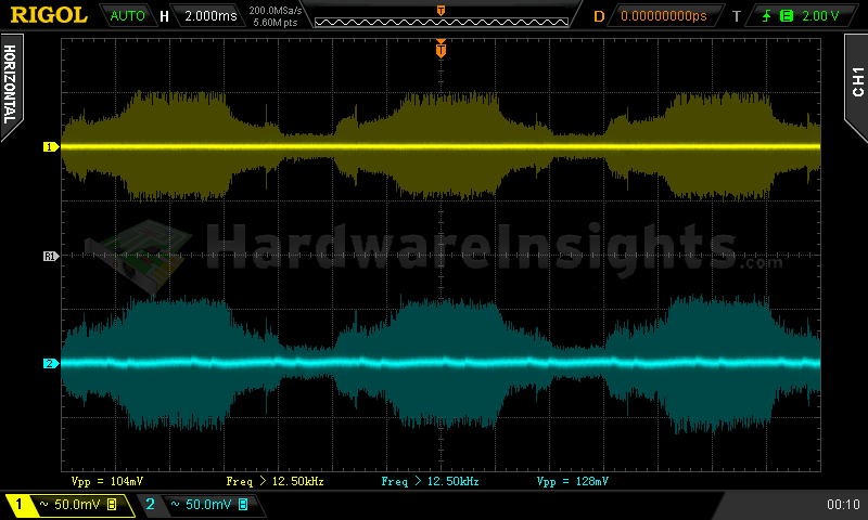
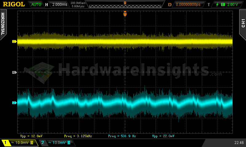
Ripple 100% load (left to right): +5 V SB; +3.3 V; +5 V; −12 V. The second channel is connected to +12 V.
Crossloading, overloading
Crossloading tests really stressed the group-design aspect here, as was expected. This time I had to severely increase the load on the +12 V rail during +5 V rail crossload, otherwise the voltage was too high at approx. 12.7 V. But even according to Intel’s ATX specification at least for 450W units, at approx. 120 W combined on +3.3 and +5 V rails, the draw from +12 V rail must be at least 120 W. So after increasing the draw to about 120 W, the voltage finally dropped back to allowed maximum of 12.60 V. Still not spectacular regulation though. Crossload efficiency was quite low. Trying to overload different rails hit dead end – clearly the unit really has no OCP capability.
| Output power | Load/ voltage +5 V SB | Load/ voltage +3.3 V | Load/ voltage +5 V | Load/ voltage +12 V | Load/ voltage −12 V | Input power | Efficiency/power factor |
| 17 %/ 102.89 W | 0.544 A/ 5.09 V | 21.64 A/ 3.37 V | 0.314 A/ 5.14 V | 1.833 A/ 12.07 V | 0.299 A/ −11.56 V | 143.0 W | 72.0 %/ 0.91 |
| 39 %/ 235.41 W | 0.535 A/ 5.08 V | 1.508 A/ 3.36 V | 21.8 A/ 4.78 V | 9.50 A/ 12.60 V | 0.304 A/ −12.24 V | 286.2 W | 82.3 %/ 0.96 |
| 89 %/ 536.74 W | 0.545 A/ 5.07 V | 1.538 A/ 3.36 V | 1.527 A/ 5.24 V | 44.2 A/ 11.70 V | 0.309 A/ −11.86 V | 635.3 W | 84.5 %/ 0.98 |
| 138 %/ 830.96 W | 3.26 A/ 4.87 V | 23.0 A/ 3.32 V | 22.9 A/ 4.80 V | 51.1 A/ 12.23 V | 0.315 A/ −12.48 V | 1065.8 W | 77.8 %/ 0.98 |
Once again the OPP kicked in about the value which has been advertised, this time it was 830 W. I had to push my load pretty hard and clearly the unit could use little more load on the +12 V rail ![]() The efficiency was already pretty poor under this scenario and the unit was running hot. But all voltages were still within allowed limits. As for the Sweater test, the unit managed to work for ordinary 15 minutes, by the end it was smelling really really bad. Upon opening the sweater, I was able to measure the fan speed at around 1700 RPM, and the exhaust temperature at over 73 °C. This is really too much. It must have been much hotter than that inside, and I bet that if I had left the sweater on any longer, the unit would have caught fire or “just” blown up.
The efficiency was already pretty poor under this scenario and the unit was running hot. But all voltages were still within allowed limits. As for the Sweater test, the unit managed to work for ordinary 15 minutes, by the end it was smelling really really bad. Upon opening the sweater, I was able to measure the fan speed at around 1700 RPM, and the exhaust temperature at over 73 °C. This is really too much. It must have been much hotter than that inside, and I bet that if I had left the sweater on any longer, the unit would have caught fire or “just” blown up.
Crossloading, overloading ripple
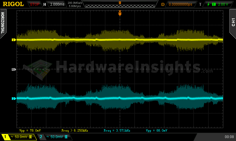
Well, the ripple was definitely not within spec, especially during the +12 V crossloading test.
| Output % | Ripple +5 V SB | Ripple +3.3 V | Ripple +5 V | Ripple +12 V | Ripple −12 V |
| 17 | 14.0 mV | 14.8 mV | 14.8 mV | 24.0 mV | 23.3 mV |
| 39 | 35.2 mV | 33.6 mV | 17.2 mV | 71.2 mV | 40.8 mV |
| 89 | 102.0 mV | 122.0 mV | 86.0 mV | 82.0 mV | 61.3 mV |
| 138 | 154 mV | — | — | 69.6 mV | — |
Fan speed and temperatures
This unit’s fan started spinning right after turning the PSU on. During the first three tests, the speed was roughly 650-700 RPM, then it started increasing approximately by 300 RPM after each test.
| Output % | Fan speed (RPM) | Temperature intake/ outtake |
| 4.5 | 658 | 22 °C/ 25 °C |
| 20 | 660 | 23 °C/ 27 °C |
| 40 | 716 | 25 °C/ 33 °C |
| 60 | 994 | 25 °C/ 34 °C |
| 80 | 1266 | 25 °C/ 37 °C |
| 100 | 1611 | 27 °C/ 42 °C |
| CL 17 | 1197 | 25 °C/ 34 °C |
| CL 39 | 1170 | 25 °C/ 33 °C |
| CL 89 | 1391 | 25 °C/ 39 °C |
| OL 138 | 1773 | 26 °C/ 55+ °C |
The temperatures are mostly the same as with the 500W version, just the highest air temperature measured at the exhaust was at over 55 °C. I would be afraid to use this in much more than 30 °C ambient temperature with bad case cooling, and even under these conditions it would already mean pushing the unit. At least it does have quality capacitors though which should survive very long even at these higher temperatures.

