Contents
- 1Introducing the Super Flower Leadex Platinum 750 W
- 1.1Packaging and accessories
- 2Connectors & cabling
- 2.1Casing & cooling
- 3Input filtering
- 4Primary side
- 4.1+5 V stand-by rail
- 5Secondary side
- 5.1Build quality
- 6Load testing
- 6.1Loading +5 V SB
- 6.2Voltage hold-up time
- 6.3Combined loading
- 6.4Combined loading ripple
- 6.5Crossloading, overloading
- 6.6Crossloading, overloading ripple
- 6.7Fan speed, temperatures and noise
- 7Conclusion and evaluation
- 7.1Thanks
- 7.2Discussion
Primary side
The Leadex Platinum 750 W as well as the whole Leadex family and it’s derivatives use special layout, so lets first talk about this. First we have the input filtering stage by the very right side. The power flows from top to bottom where it turns left for the PFC section (the bottom big coil with transformer EE core) and flows back to the top where is the switching section (the two transistors with tiny heatsinks and main transformer. Then we jump to the secondary side with rectification and as we move down, the DC-DC converters section and finally the stand-by supply and fan logics. Then the high currents only travel very short distance for the output modular connectors. While this layout is uncommon, it is very effective in the end. Just look at the tiny heatsinks the two switching transistors use! Those things move almost a kilowatt of power! I still remember seeing such heatsinks in old CRT displays where the silicon mounted to them only had few tens of watts through it and even then it got hot as hell…
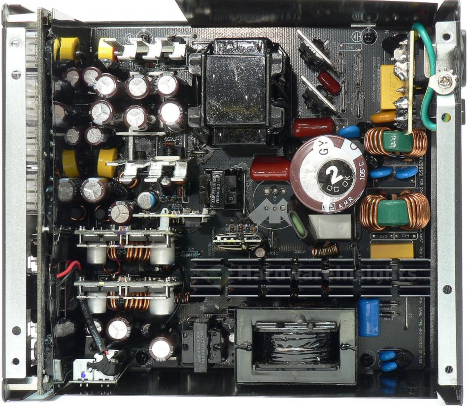
Besides the layout itself, the primary side is the same as usual. We have an input rectifier, the Shindengen US30KB80R capable of delivering 30 A continuous at 97 °C (or 1000 A peak for 1 ms at 25 °C) at 800 V. The maximum voltage drop is 1.1 V per diode (at 15 A). It is mounted on the common, large black anodized primary heatsink, with no thermal grease. The PFC transistors are Infineon IPA50R199CP (17/40 A at 550 V and 25 °C, Rds(On) 0.199 Ω at 9.9 A and 25 °C, 0.45 Ω at 150 °C) in TO-220FP package. The diode is the Cree C3D08065I (15.2/69 A at 25 °C and 650 V, drop of 2.4 V at 8 A and 175 °C) in TO-220-2 package. All the power silicon is mounted on the common heatsink together with the bridge rectifier. The large inductor acting as the PFC coil then charges the Chemi-Con KMR 680 μF/400 V capacitor (measures 618 μF). It is quite large and as can be seen, there are spots for two (for higher-power versions of this platform), but in such case, two capacitors with smaller diameter (thus lower capacitance each) must be used. (Or the second one must be even smaller to fit next to this D30×50 mm one). The KMR series is rated for 2000 hours at 105 °C and maximum ripple.
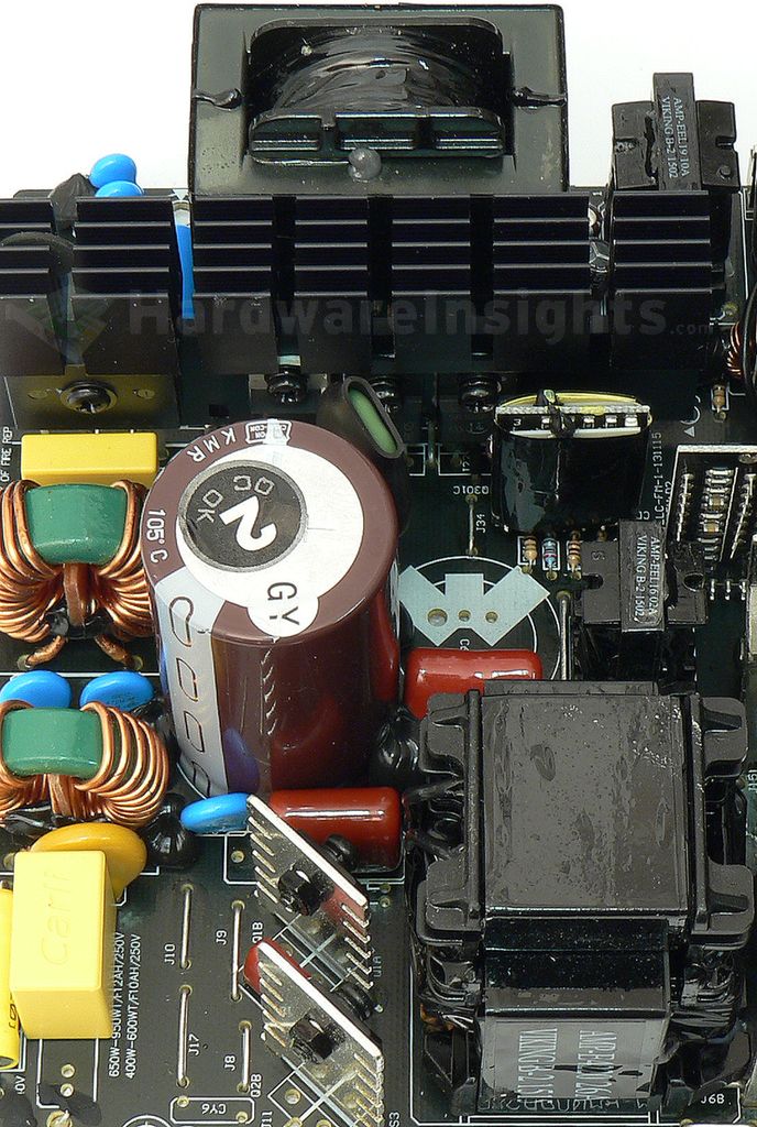
The switching transistors in half-bridge configuration are two Infineon IPA50R140CP (23/56 A at 25 °C and 550 V, Rds(On) 0.14 Ω @14 A/25 °C and 0.32 Ω @150 °C) in TO-220FP package. Compared to the 199 used in PFC they provide lower losses. The main transformer looks strange, it is because the upper part is actually second inductor (part of the LLC resonant circuitry) glued on the top of the transformer beneath it. As for the driving ICs, the PFC is driven by ON Semiconductor NCP1653A located on that small, insulated daughterboard right from the green heatshrinked thermistor (picture above). An NCC KMG 10/50 capacitor filters its input supply feed. The resonant LLC controller is than located on yet another daughterboard just further right next to the PFC board. An AA9013 DIP-16 microchip is used which is proprietary part with no public datasheet.
+5 V stand-by rail
The stand-by supply is based on the “29604” PWM controller with integrated power MOSFET, another proprietary microchip. Two more KMG caps are filtering its power input. As we have already established, it is fed directly from the input filtering section. It uses EEL-19 transformer to transfer the power to it’s low side.
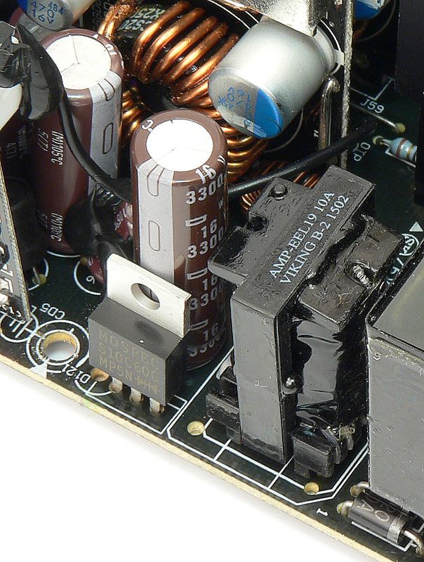
There’s the MOSPEC S10C60C (10/125 A at 150 °C and 60 V, drop of 0.7 V at 25 °C) Schottky rectifier in TO-220 package and with no heatsink whatsoever. As for filtering, we have a single tall Chemi-Con “W” 3300/16 (much like my custom KZN 3300/16 D10×40 mm) and single KY 1000/16 after the Pi coil.

