Contents
- 1Introduction
- 1.1Packaging and accessories
- 2Connectors & cabling
- 2.1Casing & cooling
- 3Input filtering
- 4Primary side
- 4.1+5 V stand-by rail
- 5Secondary side
- 5.1Build quality
- 6Load testing
- 6.1Loading +5 V SB
- 6.2Voltage hold-up time
- 6.3Combined loading
- 6.4Combined loading ripple
- 6.5Crossloading, overloading
- 6.6Crossloading, overloading ripple
- 6.7Fan speed and temperatures
- 7Conclusion and evaluation
- 7.1Thanks
- 7.2Discussion
Primary side
The primary side starts with a bridge rectifier, the Shindengen LL15XB60. It can handle a continuous current of 15 A when heatsinked and running at under the maximum of 124 °C @ 600 V, or 630 A surge (1 ms) at 25 °C. The voltage drop is 0.9 V per diode at 7.5 A. There are two ST Micro STF18N60M2 transistors (13/52 A at 600 V and 25 °C, Rds(On) is 0.28 Ω at 6.5 A) in TO-220FP package in the boost-type PFC circuit. The “18” in the model number is a bit misleading on the part of STMicro, as one would assume that the “18” denotes an 18 A part(as is typically the case), but the reality is is that it’s just a 13A part. The diode in PFC is a Cree C3D4060 (13.5/220 A at 25 °C and 600 V, voltage drop is 2.4 V at 4 A and 175 °C) in a TO-220-2 package. The PFC coil seems “beefy” enough (plus it is extra insulated using two seperate pieces of insulation tape). There are two input capacitors in parallel, both are Rubycon MXG 220 μF/450 V rated at 105 °C. This series has a lifetime of 3000 hours at the maximum temperature and ripple capacity (But it should lasts significantly longer in real-world usage scenarios).
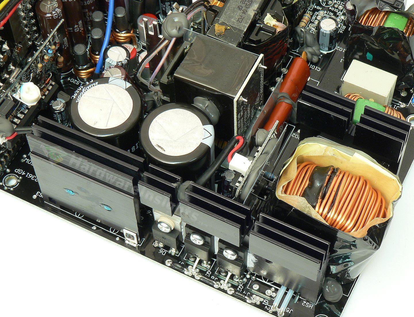
Right between the coil and the capacitors is a PFC board which carries the well hidden Infineon ICE1PCS02 PFC controller. There is one Toshin Kogyo 10/50 capacitor and one Rubycon YXG 47/25 capacitor nearby. I will remark that this particular IC is already showing its age. There are two more ICs nearby (an LM393NG comparator and an LM358N amplifier). Next, there’s a special Power Integrations disconnect IC on the solder side directly under the PFC board. It’s intended purpose is to disconnect different kinds of circuitry from the power source and reduce the power consumption at stand-by or at very low load conditions. This IC bears the SEN013DG marking. If I am not completely mistaken (as I have not personally seen it), the original FSP platform used a full-bridge topology, but this one has a half-bridge LLC topology with a three-way switching mode (FM+2 PWM modes) depending on the load.
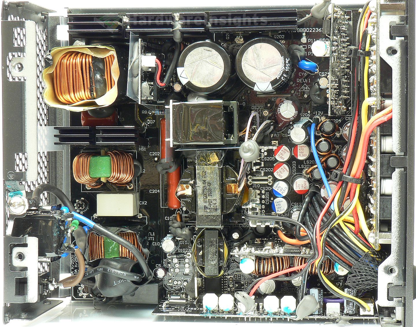
The unit uses the Champion Micro CM6901T2X (which we’re familiar with), physically located on the secondary side. It controls two identical transistors, which are the STMicro STF22NM60N (16/64 A at 600 V and 25 °C, Rds(On) 0.22 Ω at 6 A) and they come in a TO-220FP package. Both are mounted on the common primary black heatsink on the inner side (while the PFC silicon is mounted on the outer side). The main transformer isn’t as large, as it only uses a 36mm core, and the larger adjacent one is actually the coil for the LLC circuitry. It is soldered to a daughterboard, which has “P11-750W” printed on it.
+5 V stand-by rail
The stand-by rail uses some kind of controller in a package which is unfamiliar to me. It is the Power Integrations SC1225K for which I could find no datasheet for, although one source claims it is supposed to be a 4A rated controller. Its transformer has a 23mm core.
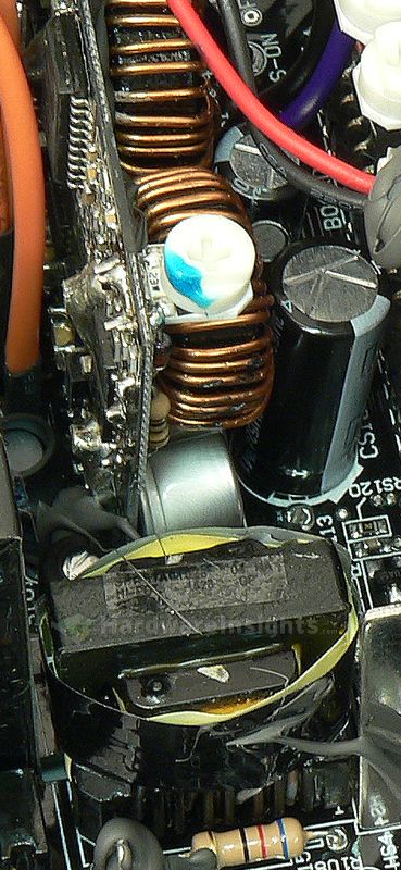
There’s a single DO-package diode for single-way rectification together with the International Rectifier IRFR1018EPbF (56/315 A at 60 V and 25 °C, Rds(On)8.4 mΩ at 47 A) transistor in a TO-252 package. It seems to effect some sort of semi-synchronous rectification. Heat from the transistor is transfered through a silicone pad to the units casing. Two Rubycon ZLH capacitors are used for filtering, a 2200/10 and a 1500/10.

