Contents
- 1Introducing the Zalman ZM600-GVM
- 1.1Packaging and accessories
- 2Connectors & cabling
- 2.1Casing & cooling
- 3Input filtering
- 4Primary side
- 4.1+5 V stand-by rail
- 5Secondary side
- 5.1Build quality
- 6Load testing
- 6.1Loading +5 V SB
- 6.2Voltage hold-up time
- 6.3Combined loading
- 6.4Combined loading ripple
- 6.5Crossloading, overloading
- 6.6Crossloading, overloading ripple
- 6.7Fan speed and temperatures
- 7Conclusion and evaluation
- 7.1Thanks
- 7.2Discussion
Primary side
The primary side starts with a beefier bridge rectifier, the GBU1006, which has its own aluminium heatsink. It can handle a continuous current of 10 A when heatsinked and running at under the maximum of 100 °C @ 800 V, or 220 A surge (8.3 ms) at 25 °C. The voltage drop is 1.1 V per diode at 10 A. There are two Infineon IPA60R190P6 transistors (20.2/57 A at 600 V and 25 °C, Rds(On) is 0.19 Ω at 7.6 A and 25 °C, 0.445 Ω at 150 °C) in a TO-220FP package in the boost-type PFC circuit. These are about twice as good as the ones in the less-powerful sibling. It is also worth mentioning this is third version of 60R190 transistors we see. The diode in the PFC is an NXP BYC10-600 (10/71 A at 25 °C and 600 V, voltage drop is 2.9 V at 10 A and 25 °C, 1.8 V at 150 °C) in a TO-220-2 package. The PFC coil seems better-sized this time and it also uses thicker wire for winding.
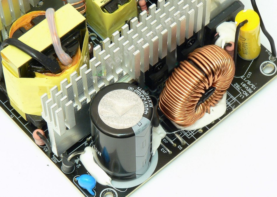
The capacitor which is charged from the PFC is a Rubycon this time, the MXH Series 330 μF/400 V. This series has lifetime of 2000 hours at 105 °C when running at its maximum ripple spec. Basically the same as the Chemi-Con before. Two Champion Micro ICs are located on the solder side, quite close to each other: The first is the 10-pin CM6805BG combo controller which controls both the PFC and PWM switching. The second is the CM03X which lowers the power consumption when there is no load (or as CM refers to this, “phantom power”). Two Chemi-Con capacitors filter the 6805’s supply power, a KMG 47/50 and a KY 10/50. This IC then controls two Magnachip MDP18N50 transistors (18/72 A at 25 °C and 500 V, Rds(On) 0.27 Ω at 9 A) in a TO-220 package, in a forward configuration. This time the common primary side heatsink has more fins as it will dissipate somewhat more heat.
The main transformer has a 36 mm wide core. Overall I would say that the silicon they’ve used so far is only average by mainstream unit standards. The PFC silicon is rated much higher than before, most likely because it has to charge capacitor of the same capacity as before and also to keep losses down. On the other hand, the switching silicon is the same so for 600W unit it is not that much over-spec’d as for 500W one, so we shall see how it performs.
+5 V stand-by rail
The stand-by supply is exactly the same: some very small 6pin PWM controller is used to drive the stand-by rail. It is labeled 09 D0T, and I have no idea what it is. But it drives a single MOSFET, the Unisonic Technologies 2N60L (2/8 A at 25 °C and 600 V, Rds(On) 5 Ω) in a TO-220F package with no heatsink. The transformer uses an 18mm core.

There’s a single DO-package diode for single-way rectification. Two Chemi-Con caps are used for filtering, both KY Series 1000/10.

