Contents
- 1Introducing the Silverstone Strider Titanium 600 W (SST-ST60F-TI)
- 1.1Packaging and accessories
- 2Connectors & cabling
- 2.1Casing & cooling
- 3Input filtering
- 4Primary side
- 4.1+5 V stand-by rail
- 5Secondary side
- 5.1Build quality
- 6Load testing
- 6.1Loading +5 V SB
- 6.2Hold-up time
- 6.3Combined loading
- 6.4Combined loading ripple
- 6.5Crossloading, overloading
- 6.6Crossloading, overloading ripple
- 6.7Fan speed, temperatures and noise
- 7Conclusion and evaluation
- 7.1Thanks
- 7.2Discussion
Primary side
The primary side begins with the input bridge rectifiers (two of them in parallel), the Vishay BU1506. They can handle 15 A continuously at 600 V and 80 °C, or 200 A peak (for 8.3 ms). The voltage drop is 0.97 V per diode at 7.5 A. Both are attached to a large common primary heatsink. Then there is a PFC choke in the shape of a transformer with most of the winding hidden inside of the core. The circuit operating the PFC consists of two transistors, the Infineon IPP50R140CP (23/56 A at 550 V and 25 °C, RDS(On) 0.140 Ω at 14 A and 25 °C, 0.32 Ω at 150 °C) in a TO-220 package. The diode is the Cree C3D8060 (23/220 A at 600 V and 25 °C, drop of 2.4 V at 175 °C or 1.8 V at 25 °C) in a TO-220AC package. I would have expected even better silicon than this in a Titanium unit, but it seems the job gets done here satisfactorily with the switching efficiency.
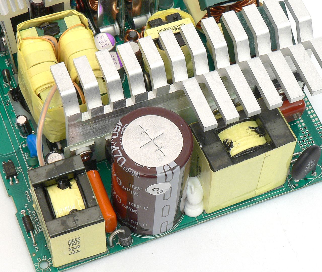
The bulk capacitor that gets charged from the PFC is a Nippon Chemi-Con KMQ 470 μF/450 V. I measured its true capacity at 418 μF. This series has a minimum lifetime of 2000 hours at maximum temperature (105 °C) and ripple. The switching transistors it feeds are the same Infineon IPP50R140CP as in the PFC, in two-transistor forward topology. The power is then sent to the secondary side through quite a unique transformer which only carries a few turns and is not really that large for a 600 W unit.
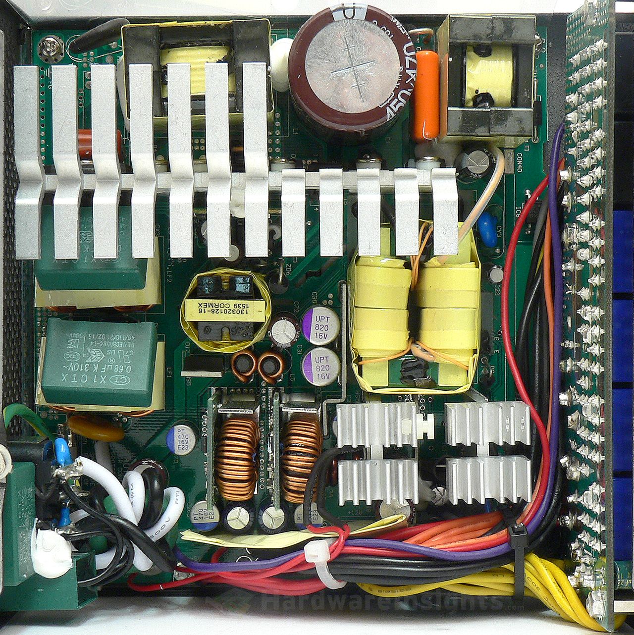
As for the driving circuitry, there is the Champion Micro CM6502TX PFC controller microchip, located on a daughterboard between the primary heatsink and stand-by transformer. There is also the CM03X IC that reduces losses on that board. As for the driving IC, we have the CM6901TBX, the latest generation of three-way switching controllers. It is physically located on secondary side, connected to the primary via the Silicon Labs Si8230BD isodriver. The feedback and power for driving ICs is mostly filtered by Rubycon ZLH or Chemi-Con KY capacitors, which are both a good and proven choice. So far, the only real good stuff I’ve seen so far in the SST-ST60F-TI.
+5 V stand-by rail
The stand-by rail in the SST-ST60F-TI uses the common SanKen Electric STR-A6069H PWM microchip with integrated transistor (RDS(On) 6 Ω). Its switching frequency is 100 kHz and with 230V input it is designed to accommodate up to 10 W. But it can usually deliver 12.5 W just fine. A transformer with 20mm core is used.
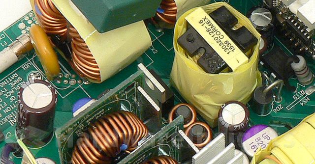
A rectifier from PFC Device Corporation is used, the PFR10V45CT (10/200 A at 45 V and 25 °C, drop of 0.46 V at 5 A) in a TO-220 package. Just standing there with no insulation or cooling, both diodes are in parallel. Two capacitors in parallel are used for filtering with no coil, one is a 470 μF/16 V PT series polymer from CapXon, the other one is wet-electrolytic Chemi-Con KZH 1500/16. To increase the efficiency under main units operation, the stand-by rail is fed from the +5 V rail through a SG30N04D MOSFET in an SMD TO-252 package. I was not able to find the datasheet but it is some generic clone of 30 A/40 V transistor.

