Contents
- 1Introducing the Linkworld LPW1685-70
- 1.1Packaging and accessories
- 2Connectors & cabling
- 2.1Casing & cooling
- 3Input filtering
- 4Primary side
- 4.1+5 V stand-by rail
- 5Secondary side
- 5.1Build quality
- 6Load testing
- 6.1Loading +5 V SB
- 6.2Hold-up time
- 6.3Combined loading
- 6.4Combined loading ripple
- 6.5Crossloading, overloading
- 6.6Crossloading, overloading ripple
- 6.7Fan speed, temperatures and noise
- 7Conclusion and evaluation
- 7.1Thanks
- 7.2Discussion
Secondary side
On the secondary side of the LPW1685-70 we can observe the usual scenery: a +3.3 V magamp and a couple of TO-220 schottky rectifiers. There are four MBR30L60CT (30/220 A at 60 V and 25 °C, drop of 0.60 V at 15 A and 25 °C, 0.56 V at 125 °C) in parallel for the +12 V. For both the +3.3 V and +5 V there is the same part, a single piece for each rail. It is the PFC Device Corporation PFR30L45CT (30/250 A at 45 V and 125 °C, 0.52 V at 25 °C and 15 A). All these semiconductors use the same common secondary side heatsink. A small thermistor probe which provides sensing for the fan controller is screwed to it. An STB1277 PNP transistor in TO-226 package functions as the linear regulator for the fan. The common inductors seem like they can just about handle the job, but using bigger ones would definitely help.
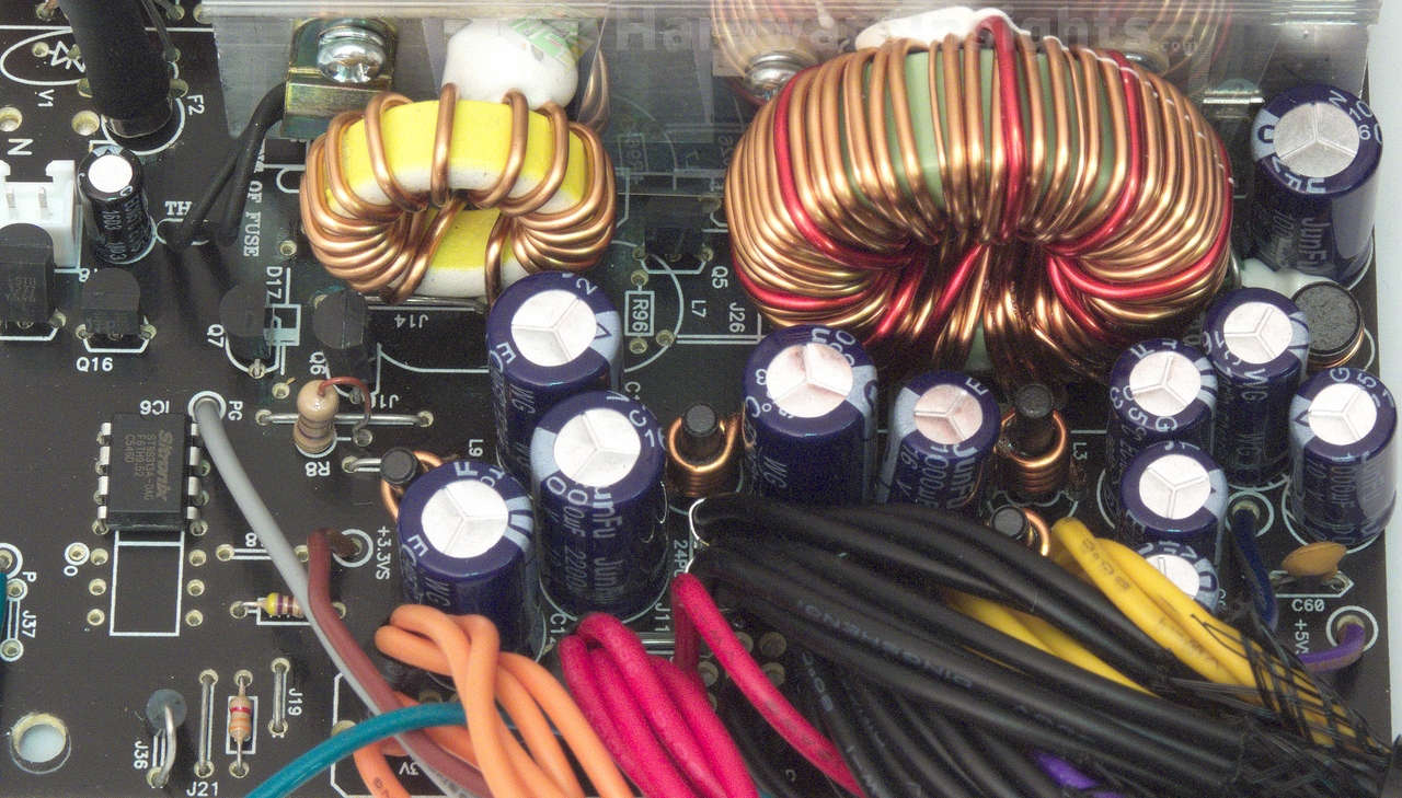
As for the filtering, the LPW1685-70 has more JunFu WG caps. There are two 1000/16 for the +12 V before Pi coil, and one more 1000/16 for each rail after their coils. Both the other positive rails have two 2200/10 caps each. Another 1000/16 then filters the −12 V rail. There are also SMD ceramic capacitors under each of the electrolytic caps, but I am not sure if this is going to help keeping the ripple in spec. Comparing with some high-end units which easily have five times the capacity… The presence of only DIP-8 secondary supervisor suggests we only have OVP, UVP, SCP and the basic functions here. A specification table for the part in use, Sitronix ST9S313A-DAG, confirms it. It is worth noting all the feedback components are there, all it needs is the DIP-14 chip and some wire jumpers. In such case the PCIe cable would be on separate rail while all the other +12V cables would be on the other.
Build quality
As usual, I’ll focus on the overall build quality and other things like electrical safety here, as the quality of the components in use was already discussed before. The separation between the primary and secondary sides is good. There is even some extra drilling under the optocouplers and the main transformer for extra cooling and anti-tracking. Not only is there an insulative film under the board, but also a rubber pad, which helps carrying the weight of the board in its center. Many of the leads were trimmed quite poorly and kept long, and this is something which I’d like to see them improve upon. The thermistor which is present lacks heatshrink insulation over it. Linkworld used the proper type silicone in quite small quantities which is nice, the unit is now clean and opened for better cooling.
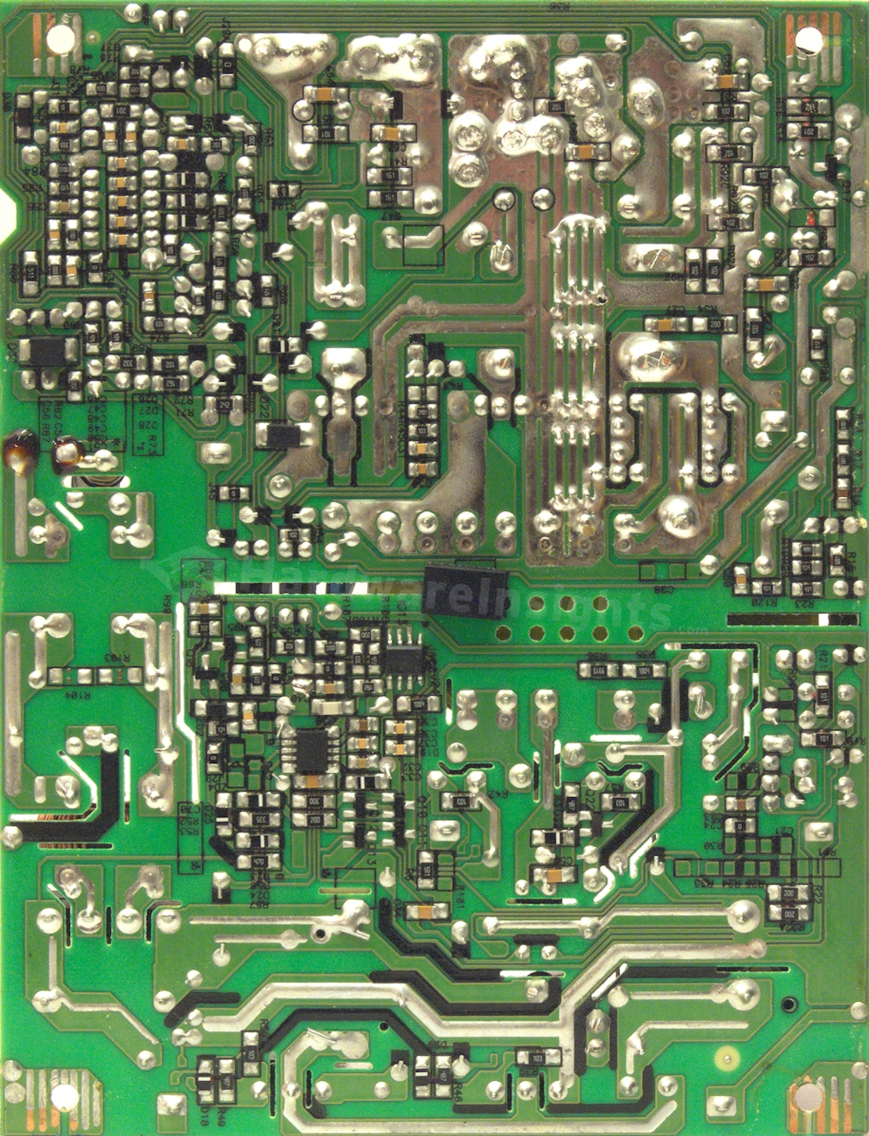
The paths on the secondary side are also reinforced with some extra layers of solder. The return path also has extra wire jumpers. Besides the four grounding pads in the corners of the board, the soldering is really great. I found no apparent problems nor even factory-resoldered joints. The board is very clean and there are no solder balls as far as I can see. For low-end unit this is just great result. If the unit passes the loading, it surely deserves the full 10 points. Nice work Andyson/Linkworld!

