Contents
- 1Introducing the Linkworld LPW1685-70
- 1.1Packaging and accessories
- 2Connectors & cabling
- 2.1Casing & cooling
- 3Input filtering
- 4Primary side
- 4.1+5 V stand-by rail
- 5Secondary side
- 5.1Build quality
- 6Load testing
- 6.1Loading +5 V SB
- 6.2Hold-up time
- 6.3Combined loading
- 6.4Combined loading ripple
- 6.5Crossloading, overloading
- 6.6Crossloading, overloading ripple
- 6.7Fan speed, temperatures and noise
- 7Conclusion and evaluation
- 7.1Thanks
- 7.2Discussion
Load testing
Loading +5 V SB
As always, all load testing is done according to our testing methodology. It seems the stand-by rail is quite soft in this unit, most likely because of rather small transformer. It starts at 5.17 V but drops under 5 V at full load. The efficiency is also on the lower side of things.
| Output (W) | Load (A) | Voltage (V)/ ripple (mV) | Input (W) | Efficiency/power factor |
| 0 | 0 | 5.17/3.680 | 0 | —/0.003 |
| 12.02 | 2.41 | 4.98/6.960 | 17.45 | 68.9 %/0.411 |
| 16.42 | 3.35 | 4.90/7.760 | 24.06 | 68.2 %/0.471 |
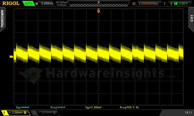
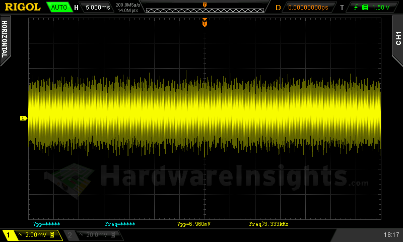
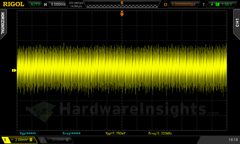
+5 V SB ripple (left to right): 0 A; 2.41 A; 3.35 A
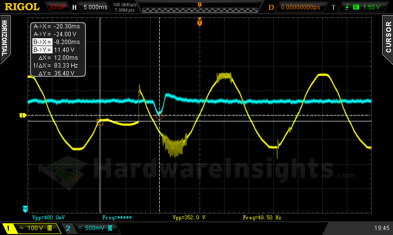
Hold-up time
As we can see on the oscilloscope screenshot, the hold-up time of the LPW1685-70 +12 V rail is quite low, just 10.36 ms.
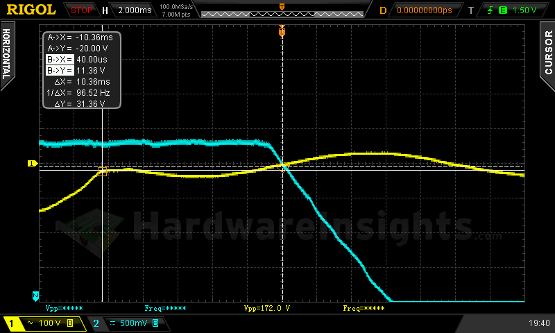
The hold-up time of the power good signal is even shorter at only 8.12 ms. This is way too low, the unit FAILS here.
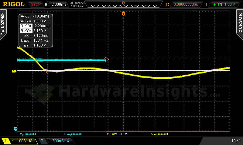
The response on precise interruption is not good. First the voltage plummeted and than spiked. To keep the voltage in spec I had to lower the time settings to under 8 ms. My estimate is this units needs at least 470μF input capacitor to at least go near the ATX specification. While it is always nice to see quality cap in any unit, this time I would recommend replacing the Hitachi capacitor with Teapo 470/420. Nobody really expects any quality components in such cheap power supplies like the LPW1685-70 is, but performing in spec would be a nice advantage.
Combined loading
Combined loading of the LPW1685-70 was OK, which is slightly surprising in this price segment. The unit was able to deliver the rated power just fine, so lets talk about the voltage regulation first. The base +12V rail voltage was lower because of which it then fell lower, under full load to just over 11.7 V. But the +5 V SB is even worse in this matter, the voltage lowered 0.28 V so the load regulation is on the worse side. Line regulation is 3.2 % so that’s reasonable.
| Output power | Load/ voltage +5 V SB | Load/ voltage +3.3 V | Load/ voltage +5 V | Load/ voltage +12 V | Load/ voltage −12 V | Input power | Efficiency/ power factor |
| 4.2 %/ 29.22 W | 0 A/ 5.16 V | 0.017 A/ 3.37 V | 0.414 A/ 5.18 V | 1.880 A/ 12.01 V | 0.387 A/ −11.48 V | 43.04 W | 67.9 %/ 0.577 |
| 20 %/ 137.45 W | 0.538 A/ 5.09 V | 2.86 A/ 3.35 V | 2.35 A/ 5.14 V | 9.07 A/ 11.96 V | 0.393 A/ −11.64 V | 166.0 W | 82.8 %/ 0.957 |
| 40 %/ 278.01 W | 1.01 A/ 5.03 V | 4.04 A/ 3.33 V | 3.50 A/ 5.13 V | 19.97 A/ 11.86 V | 0.398 A/ −11.74 V | 329.0 W | 84.5 %/ 0.981 |
| 60 %/ 410.15 W | 1.50 A/ 4.97 V | 5.87 A/ 3.32 V | 5.95 A/ 5.09 V | 29.5 A/ 11.80 V | 0.405 A/ −11.86 V | 491.6 W | 83.4 %/ 0.988 |
|
80 %/ 556.72 W |
1.83 A/ 4.93 V | 7.43 A/ 3.31 V | 9.31 A/ 5.05 V | 40.1 A/ 11.75 V | 0.408 A/ −12.04 V | 687.3 W | 81.0 %/ 0.992 |
| 100 %/ 707.49 W | 2.29 A/ 4.88 V | 10.74 A/ 3.31 V | 11.24 A/ 5.06 V | 51.1 A/ 11.72 V | 0.412 A/ −12.17 V | 883.9 W | 80.0 %/ 0.993 |
The efficiency seems OK, I think this unit can really deliver 80 PLUS Bronze, at 230 V for sure. The low-load efficiency is somewhat worse and it also seems like the PFC is not yet running at that time as the power factor is still low. That may be the result of using cheaper CM6805 controller while also trying to keep the low-load consumption as low as possible.
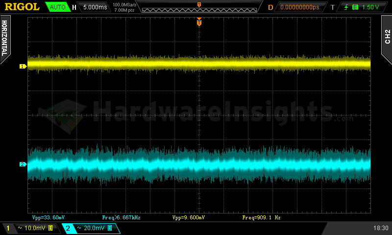
Combined loading ripple
As for the ripple, the Linkworld LPW1685-70 does not really do very good job. It pretty much skyrockets immediately upon putting some significant load on the unit. The +5 V SB rail was bordering on the 50mV specification most of the time, but lets close one eye, absolute most of the low-end units do not even provide their rated power. These figures are so high I would not recommend using the unit anyway.
| Output % | Ripple +5 V SB | Ripple +3.3 V | Ripple +5 V | Ripple +12 V | Ripple −12 V |
| 4.2 | 19.20 mV | 9.600 mV | 12.40 mV | 33.60 mV | 18.40 mV |
| 20 | 39.20 mV | 36.80 mV | 33.60 mV | 68.00 mV | 48.00 mV |
| 40 | 38.40 mV | 39.20 mV | 40.00 mV | 86.00 mV | 42.40 mV |
| 60 | 48.80 mV | 38.40 mV | 41.60 mV | 80.00 mV | 44.80 mV |
| 80 | 49.60 mV | 41.60 mV | 43.20 mV | 94.60 mV | 68.00 mV |
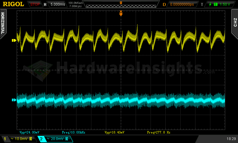
| 100 | 49.60 mV | 43.20 mV | 46.40 mV | 100.0 mV | 63.20 mV |
As I stated in previous chapter, I believe that the LPW1685-70 could use much greater capacitance on its output. But also using bigger secondary coils would help. It is primarily the role of the inductors (just after the rectifiers) to store the energy when the primary transistors are off, for the forward topology units. When the size is inadequate, the ripple increases (among other things).
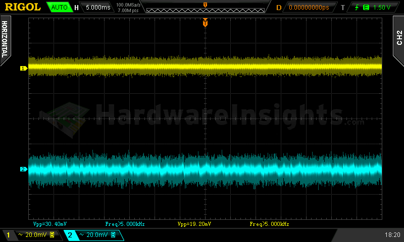
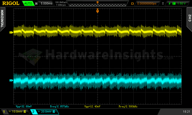
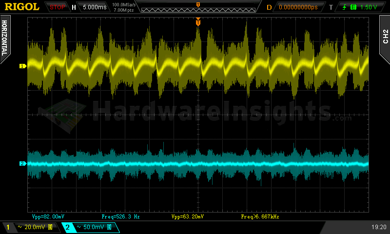
Ripple 4.2% load (left to right): +5 V SB; +3.3 V; +5 V; −12 V. The second channel is connected to +12 V.
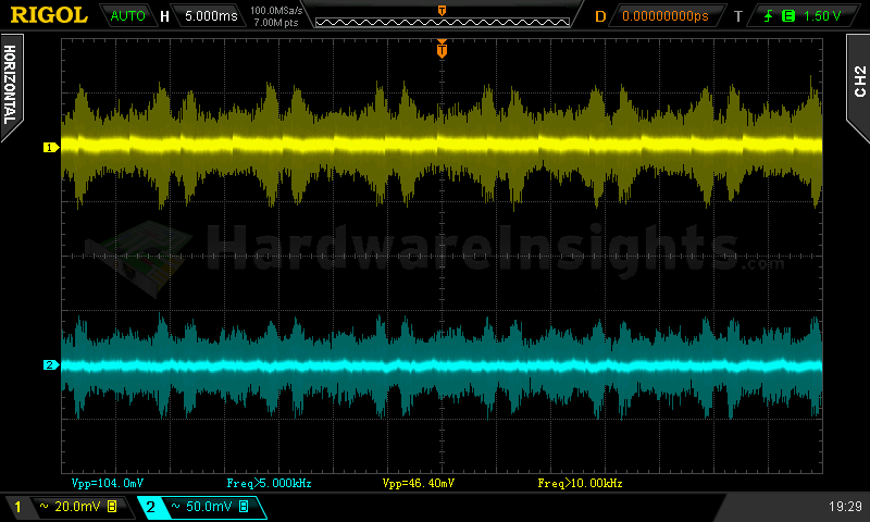
Ripple 100% load (left to right): +5 V SB; +3.3 V; +5 V; −12 V. The second channel is connected to +12 V.
Crossloading, overloading
As this is ordinary group-design platform, the crossloading is expected to be mediocre at best. Crossloading the +3.3V rail was OK, surprisingly also the +5 V rail. Most likely thanks to the fact the +12 V rail was set slightly lower. However, while crossloading this main rail with minimum output from the others the voltage fell too low. Increasing the +5 V rail output to about 3.5 A fixed it. I consider this fairly bad (but not tragic) regulation. While Linkworld does not state any minimum loading requirements for crossload, the ATX crossloading graphs usually consider at least 30 W combined draw from +3.3 and +5 V while loading the +12 V to maximum. With these figures below we are barely at 25 W. I think this result is fairly OK for a 700W unit of such price.
| Output power | Load/ voltage +5 V SB | Load/ voltage +3.3 V | Load/ voltage +5 V | Load/ voltage +12 V | Load/ voltage −12 V | Input power | Efficiency/ power factor |
| 14 %/ 99.61 W | 0.530 A/ 5.09 V | 20.03 A/ 3.34 V | 0.538 A/ 5.09 V | 1.884 A/ 12.03 V | 0.400 A/ −11.53 V | 148.1 W | 67.3 %/ 0.950 |
| 19 %/ 131.22 W | 0.535 A/ 5.09 V | 1.486 A/ 3.35 V | 19.6 A/ 4.79 V | 1.973 A/ 12.54 V | 0.391 A/ −12.03 V | 172.4 W | 76.1 %/ 0.959 |
| 91 %/ 634.55 W | 0.524 A/ 5.05 V | 1.410 A/ 3.33 V | 3.710 A/ 5.24 V | 52.6 A/ 11.46 V | 0.418 A/ −11.92 V | 780.9 W | 81.3 %/ 0.992 |
| 121 %/ 849.00 W | 3.13 A/ 4.77 V | 20.57 A/ 3.30 V | 19.95 A/ 4.97 V | 56.1 A/ 11.80 V | 0.411 A/ −12.35 V | 1105 W | 76.8 %/ 0.993 |
As the full-sized secondary supervisor has been cut out with few other corners, there is obviously no OCP. The OPP however reacted fine at about 850 watts. That means the LPW1685-70 can not only deliver rated power but over 20 % extra while keeping the voltages in spec. This is pretty impressive for the money.
Crossloading, overloading ripple
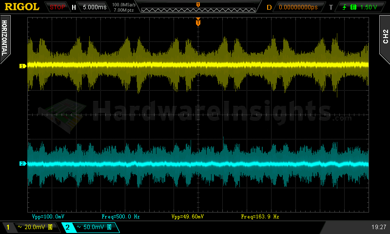
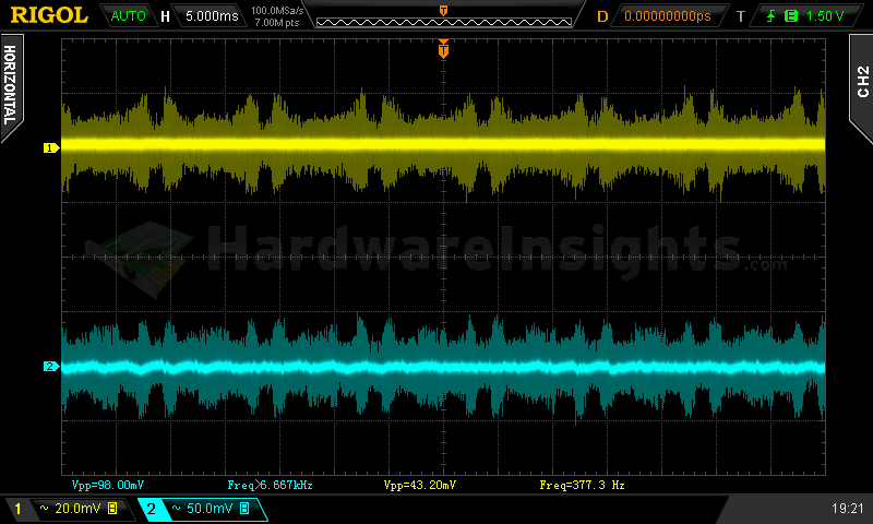
Crossloading ripple was a similar story, though under overload, with a higher output from all rails, the overall ripple dropped a tiny bit. It seems that the unit has some reserve in the switching duty cycle. So while under overload, the transistors were on for a longer time, also charging the secondary inductors for longer time. And discharging for shorter time as a result. That kept the ripple lower.
| Output % | Ripple +5 V SB | Ripple +3.3 V | Ripple +5 V | Ripple +12 V | Ripple −12 V |
| 14 | 41.60 mV | 27.20 mV | 40.00 mV | 46.00 mV | 35.20 mV |
| 19 | 41.60 mV | 36.00 mV | 36.00 mV | 56.00 mV | 35.20 mV |
| 91 | 44.80 mV | 46.40 mV | 42.40 mV | 80.00 mV | 60.00 mV |
| 121 | 48.00 mV | – | – | 86.00 mV | – |
Fan speed, temperatures and noise
The fan inside the Linkworld LPW1685-70 started spinning right when the unit powered on. It starts at reasonable speed of less than 700 RPM. However, with 38.8 dBA ambient, it is already noticeable. I blame a sloppy manufacturing quality of the fan, which made like a “clicking” noise similar to some ball-bearing fans. There are several reasons behind this, mostly to do with cheaping out the fan too much. With increasing speed, also aerodynamic noise added to that so at about 1100 RPM the unit was getting really audible and around 1500 RPM it was a tornado. This is one of the loudest units so far, competing most likely only with the Antec High Current Gamer M 750 W.
| Output % | Fan speed (RPM) | Temperature intake/ outtake | Noise (dBA) |
| 4.2 | 678 | 21 °C/ 22 °C | 38.9 |
| 20 | 706 | 21 °C/ 27 °C | 38.9 |
| 40 | 890 | 21 °C/ 30 °C | 39.3 |
| 60 | 1172 | 22 °C/ 33 °C | 40.9 |
| 80 | 1508 | 23 °C/ 35 °C | 45.1 |
| 100 | 1743 | 24 °C/ 42 °C | 49.3 |
| CL 14 | 1130 | 23 °C/ 33 °C | 40.9 |
| CL 19 | 1022 | 22 °C/ 32 °C | 39.8 |
| CL 91 | 1391 | 25 °C/ 35 °C | 43.8 |
| OL 121 | 1768 | 26 °C/ 44 °C | 49.3 |
Despite that, the unit still runs hot, which makes sense because of the small heatsinks Linkworld, Andyson or whoever put inside. The efficiency is slightly better than in the case of Zalman ZM600-LX we reviewed recently. On the other hand this unit has 100 W higher power output. It has larger fan, but slower-spinning. As always, I remind you that heat+garbage capacitors=problem. So while the unit can deliver rated power, it runs hot and very loud doing that. On the other hand, such units as this are usually for people buying according to VGA manufacturers tables. That means for example combining a 200W card with 700W power supply. For such configurations, it will never see its rated power output so most customers will glorify such units as this LPW1685-70 as silent etc. etc. just because they have no chance of loading it to the point where it is not. And because they never heard any of the noise-less semi-fanless (or with ultra-low spinning fans) units on the market…
The problem escalated under the Sweater contest. After about 10 minutes the power consumption started rising. It was a clear signal something is very wrong. My estimate is one of the four secondary +12V rectifiers dropped its forward voltage and started taking more current by itself. I was able to shut the power down in the last seconds when the speed of the shift was getting critical and also when the ripple skyrocketed. That was a signal we are just before the very moment. I had no interest in fireworks, there will be plenty of that with the coming holidays just outside of my benchroom. So while I technically prevented it, we can take it as the unit died in this test.

