Contents
- 1Introducing the Super Flower Leadex Platinum 750 W
- 1.1Packaging and accessories
- 2Connectors & cabling
- 2.1Casing & cooling
- 3Input filtering
- 4Primary side
- 4.1+5 V stand-by rail
- 5Secondary side
- 5.1Build quality
- 6Load testing
- 6.1Loading +5 V SB
- 6.2Voltage hold-up time
- 6.3Combined loading
- 6.4Combined loading ripple
- 6.5Crossloading, overloading
- 6.6Crossloading, overloading ripple
- 6.7Fan speed, temperatures and noise
- 7Conclusion and evaluation
- 7.1Thanks
- 7.2Discussion
Input filtering
This time, there is no input filtering on the AC inlet, also only single-pole switch is used (actually, a double-pole switch but with both poles paralleled for the phase). It is most likely for the purpose of saving space to increase the airflow through the backside. Moving onto the main board, we can see five ceramic Y capacitors (and spots for three more), two of them have tiny ferrite rings on them. Then there are two X film capacitors (with spot for third) and two common-mode chokes. Also a single yellow varistor (with no heatshrink insulation) and one heatshrinked flying thermistor over the bypass relay. In my opinion, it should have been the other way arround, the MOV should have been heatshrinked.
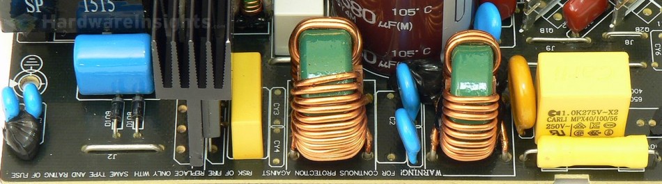
You can actually only see part of the relay on this image (next to the input capacitor). There is no X-cap discharge IC nor any discharge resistor – two diodes visible on the left side of the image rectify the AC and directly provide feed for the stand-by power supply controller IC. If the AC supply is interrupted, the IC quickly discharges the capacitors. (If it is actually working, resistors usually fail much less often than these ICs.) This is modern approach we have seen in many competitive units lately.
The X capacitors (between the live and neutral) and Y capacitors (between live and ground/neutral and ground) are used to filter out high-frequency ripple that emanates from the power grid. That is the noise of which manifests in the form of feedback from electronic devices which lack adequate filtering due to cost cutting. But also from devices where filtering was very difficult to implement (powerful devices, e.g. microwave ovens). It also prevents ripple from this unit itself from feeding back into the grid.
Chokes are used for the same reason, and together with the X/Y capacitors they form an input filter. Such filters are often made as one component, they may also be integrated together with AC receptacle. These components may also (partially) help to filter smaller voltage spikes in the power grid. To suppress more serious spikes (for example from distant lightning strikes hitting the power grid), the MOV (metal-oxide varistor) is used. Thermistor is then used to suppress current spikes when first connecting the unit to power (i.e. flipping the power switch).
The Y capacitors are also often situated between the high-voltage primary and the low-voltage secondary sides. These days, more Y capacitors are used even between primary common (ground after an input rectifier) and earth ground to suppress internal interference and keep it from getting to the secondary side. It is because really high-frequency ripple goes everywhere it can to some extent (including coupling through the insulation, metal casing etc…). That is also why the AC wires themselves are often inserted through the ferrite toroid inductor (to suppress such coupling).

